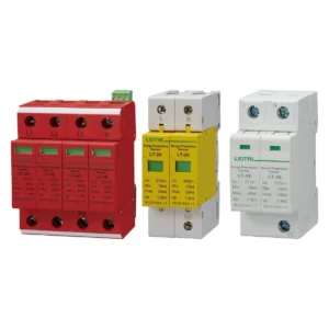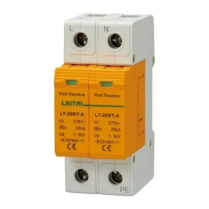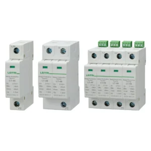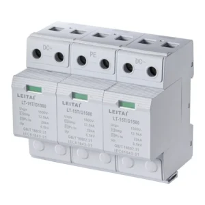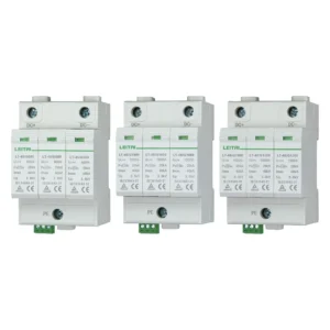

If you contact three distributors concerning a surge protector, you will normally see three quotes that deal with a certain number: 40 kA, 65 kA, and 100 kA. A person tends to associate the maximum kA value with higher electrical protection of a building. However, it is wrong to think this way. SPD types signify different purposes at different stages of installation and each one is subjected to testing with a different kind of impulse shape. Thus, the voltage at the output depends on how SPD manages the surge energy.
The guide you are about to read describes the differences between SPD Type 1 2 3 in a concise manner and focuses mainly on SPD coordination which is usually omitted when conducting standard comparisons.
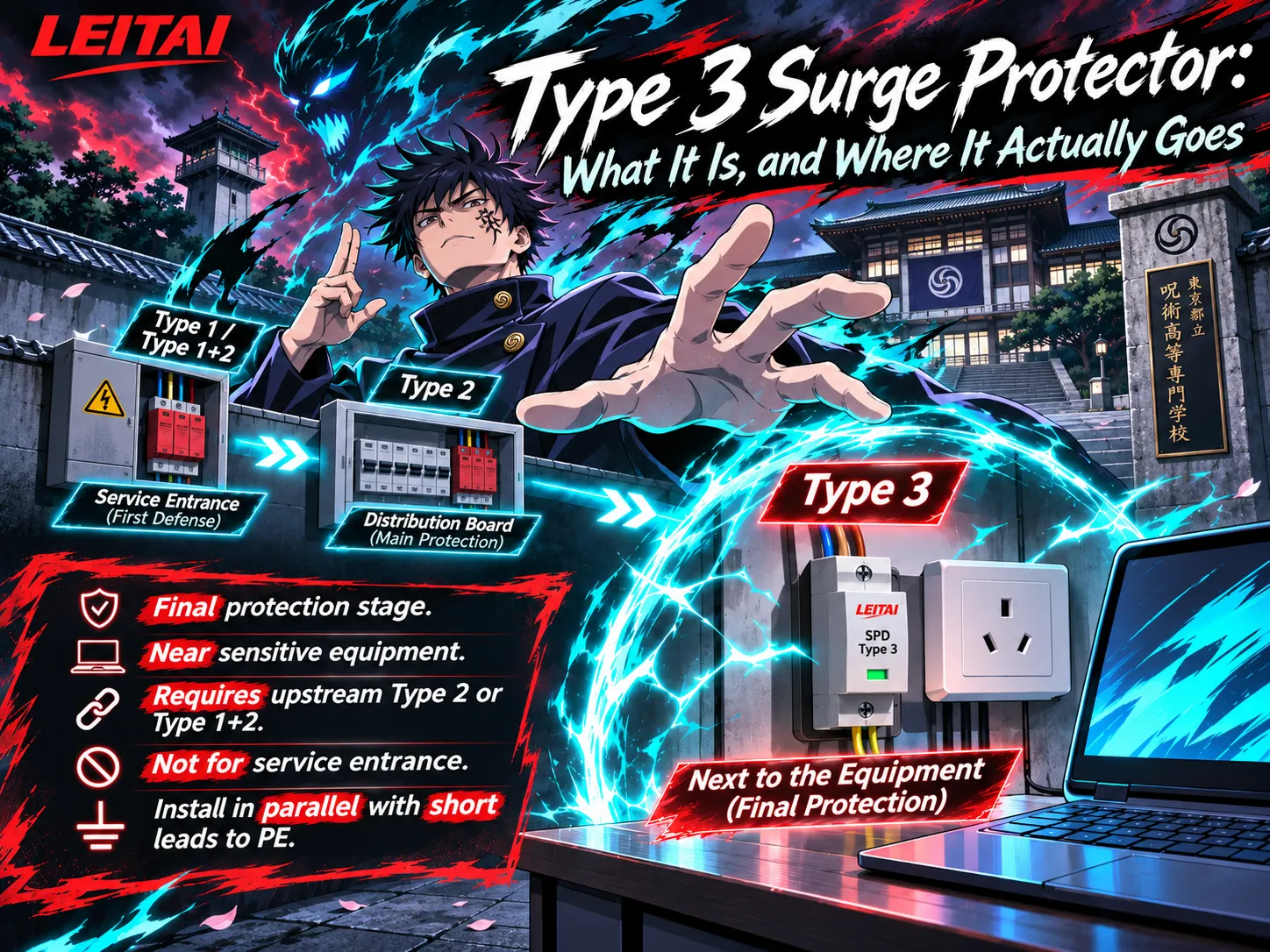
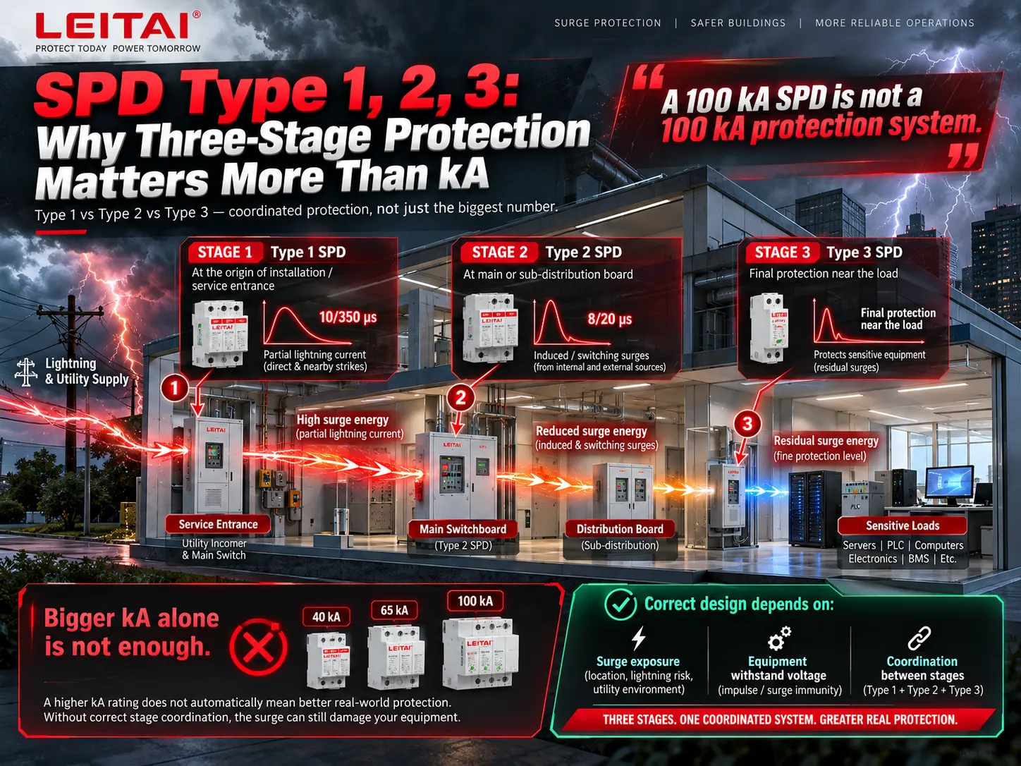
SPD Types 1, 2 and 3 are 3 different levels in surge protection processing instead of three types of quality. In IEC classification, Type 1 handles partial current of lightning at the start of the installation, Type 2 limits swirls and switching surges at distribution boards while Type 3 adds to protection. What matters while determining the right configuration is not only susceptibility to surges and impulse withstand voltage of the equipment but also coordination of devices, not the mere fact of having the highest rating of kA.
SPD Type 1 vs Type 2 vs Type 3: Key Differences
Under IEC 61643-11, the type number is a test class. It tells you which impulse the device was proven against, and that in turn decides where it belongs in the installation. The table below is the short version.
| Parameter | Type 1 (T1) | Type 2 (T2) | Type 3 (T3) |
|---|---|---|---|
| Main duty | Discharge partial lightning current | Limit induced and switching surges | Final voltage limitation at the load |
| Test impulse | 10/350 μs current | 8/20 μs current | Combination wave (1.2/50 μs voltage, 8/20 μs current) |
| Headline rating | Iimp | In and Imax | Uoc |
| Typical technology | Spark gap, or high-energy MOV | MOV, often with GDT for N-PE | MOV, MOV + GDT, filter circuits |
| Typical location | Main incoming board, service entrance | Main and sub-distribution boards | Near sensitive equipment, sockets, control panels |
| Typical Up (230/400 V) | About 1.5 to 2.5 kV | About 1.2 to 1.8 kV | About 1.0 to 1.5 kV |
Many people confuse Test Type 3 with simply “a smaller version of Type 2”. In fact, it’s a different test altogether. A combination wave generator applying a fictitious impedance equal to 2 ohm produces an open-circuit voltage of 1.2/50 µs and a short-circuit current of 8/20 µs which means that an open-circuit voltage of 6 kV is sourced by a short-circuit current of about 3 kA. Therefore, the value of open-circuit voltage is expressed in kilovolts, which is why Type 3 should be able to do cleaning after all the heavy lifting has been done by upstream stages.
If you only need the two-way comparison, the detailed Type 1 vs Type 2 SPD breakdown covers waveform energy and how to read each datasheet. This article focuses on the next question: how all three stages work as one system.
Why the Highest kA Rating Doesn’t Guarantee Better Protection
A surge protective device functions by diverting electrical current and limiting voltage. The kA rating is effective only for the first function. Damage to equipment results from failures of the second function.
Iimp vs In vs Imax: Why the Numbers Are Not Interchangeable
Iimp uses a slow 10/350µs impulse, while both In and Imax use a fast 8/20µs impulse. Thus, a 25kA 10/350µs impulse has more than 10 times more energy than the 40kA 8/20µs impulse. Therefore, a 40kA Type 2 surge protector does not equal a 25kA Type 1 but belongs to a different class. The measure In refers to the maximum current a surge protective device can endure time after time during tests, whereas the Imax refers to its single-shot ability. Thus, the number Imax refers to the service life of a surge protective device, whereas the lower the voltage, the lesser protection equipment can relay.
Why Voltage Protection Level (Up) Matters at the Load
Every device has its own volumetric withstand voltage, Uw. In installations with 230/400 V voltage IEC 60364-4-44 classifies devices into categories: Category IV devices sustain about 6 kV, Category III devices 4 kV, Category II devices 2.5 kV, and Category I devices 1.5 kV. For installations with 120/208 V voltage the categories change relative to their values, namely, 4, 2.5, 1.5, and 0.8 kV.
Protection is achieved whenever effective protection level Up,f stays below volumetric withstand voltage Uw. A typical design principle involves Up,f ≤ 0.8Uw for a surge protective device located close to equipment. A surge protective device with Up equal to 2.5 kV ensures good protection to a Category III device but it fails to protect a PLC power supply located far away approximately in the other side of the building.
How Long Connection Leads Weaken SPD Performance
The datasheet value Up is measured at the SPD terminals. The equipment sees Up plus the voltage drop on those connecting leads. Roughly, the conductor inductance of 1 μH/m adds on the order of 1 kV/m lead during a 10 kA 8/20 μs surge. Therefore, IEC 60364-5-53 requires that the total lead length (line to SPD plus SPD to earth) be no more than 0.5 m. An Up mic for 1.5 m length of loose wiring might not perform better than a rather shabby device tabbed tightly. The step-by-step surge protector wiring layout shows how to keep that loop short.
A 100 kA-rated SPD is not equal to a 100 kA-rated surge protection system; it depends on the installation position, equipment withstand voltage, and coordination among stages of the system to determine if the surge has stopped before reaching the load.
How Type 1, Type 2 and Type 3 SPDs Work Together
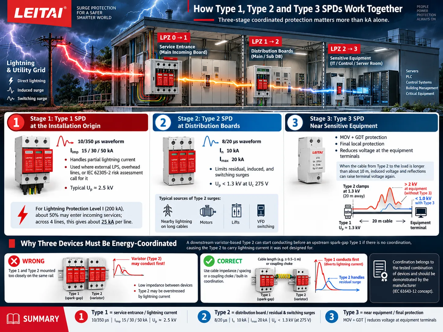
Under a cascaded setup, frequently referred to as SPD cascading, all the sections are arranged in parallel with the circuit at the point where it is installed. At the first stage, the majority of the electrical current is diverted, followed by the second stage, which regulates the amount of current that passes through, to the last stage, which is responsible for maintaining the low volts at the equipment level. In the context of IEC 62305-4, the stages are situated at the thunder protection zones borders: LPZ 0 >> 1 at the service entrance, LPZ 1 >> 2 at sub-distribution and LPZ 2 >> 3 at the area where equipment is located.
Stage 1: Type 1 SPD at the Installation Origin
In locations where there can be partial lightning impact on the electrical installation including structures with external lightning protections, installations connected to overhead lines and those marked for partial lightning protection according to IEC 62305-2, the need arises for Type 1 level. The derivation of the sizing emerges from the lightning current distribution. In IEC 62305, it is determined that around 50% of the total lightning current entering the earth system and the remaining half enters the incoming services. Therefore, with lightning protection Level 1 (200 kA), there will be about 100 kA entering the electrical line translated across four lines to give us 25 kA for each line as an outcome.
A Type 1 lightning current arrester with Iimp 15, 30 or 50 kA on the 10/350 μs waveform utilize the graphite spark gap to conduct this current. The Up of the type one level equals 2.5 kV which is suitable for the incoming board, as the first stage is operated for the handling of the lightning currents, rather than minimizing voltage output.
Stage 2: Type 2 SPD at Distribution Boards
The Type 2 device limits the flow of surge residuals allowed through the first stage, as well as allows for the handling of the surges that were never generated outside of the device; the surges that are created by neighboring lightning strikes into long lines of cables along with the ones generated in systems that are operated by motors and which use transit spikes fro lifts and variable-frequency drives. A Type 2 SPD rated In 10 kA and Imax 20 kA (8/20 μs) reaches an Up below 1.3 kV at Uc 275 V, low enough for Category II equipment fed from that board.
Stage 3: Type 3 SPD Near Sensitive Equipment
Once the cable between a Type 2 and the equipment gets longer than about 10 m, two effects push the terminal voltage up again: voltage induced into the cable loop, and reflections that can make the voltage oscillate up to roughly twice the clamped value at an open or high-impedance end. A Type 3 surge protector installed close to the load removes that distance. A compact Type 3 SPD with MOV + GDT protection has a datasheet Up of 1.5 kV, which may look higher than the 1.3 kV of the upstream Type 2. It still improves protection, because what counts is the voltage at the equipment terminals, and a Type 2 clamping at 1.3 kV twenty metres away can present well over 2 kV there.
Why Three Devices Must Be Energy-Coordinated
This is the failure mode that results in transforming three effective devices into one inefficient device. Voltage across a varistor-based device of class 2 gets lower than the spark gap device of type 1 before it can actually start to work. Assuming both devices would be placed on the same rail, the class 2 device would begin to work in advance and maintain voltage lower than spark gap ignition voltage, so the latter would not start operating, leaving the class 2 device under load of the lightning current it has not been tested for.
Surge protection coordination refers to controlling the process in a way that the devices work with power they have been designed for. The IEC 61643-12 standard embodies this idea: there should be a certain level of impedance in the circuit either because of the length of the cable or because of a coupling choke in order for the downstream device to be operational in advance. Alternatively, the manufacturer can design and run tests in such a way that devices have the built-in coupling. In both cases, the coordination is the quality of a combination of the devices, and can be shown only by the manufacturer of the devices.
SPD Coordination Distance: Do You Really Need 10 Metres?
The term “10 metres” is included in at least three distinct regulations, and confusing these terms is the reason for most of the misunderstandings in this field.
1.Decoupling distance for SPD -SPD. It is the distance for power cable between two stages that provide required impedance for energy coordination. An old catalogue provides 10.00 m for spark gap Type 1 to varistor Type 2 and 5 m for two stages of varistor. Modern devices of coordinated or fired types may need no distance at all. The distance required depends on the coordination test data provided by the manufacturer of a particular combination of devices.
2 SPD to equipment protective distance. IEC 60364-5-53 and IEC 62305-4 state that in case of SPD the distance from the protection equipment will be about 10 m. After that, oscillations and induced voltage should be emphasized, generally via another SPD near the equipment. This rule explains the usage of Type 3 and local Type 2 in devices.
3.UL 1449 Type 3 placement. In America listed types of devices are point of utilization types, which is installed at least 10 m away from the service panel. This is also an installation condition depending on the surge level the device is tested for, not energy coordination distance.
The fair conclusion can be done: two SPDs cannot be required to keep 10 m distance between them, however equipment which is located further than 10 m from the nearest SPD will require one more stage.
Type 1+2 Combined SPD vs Separate Protection Stages
A single Type 1 plus 2 Surge Protective Device (SPD) caters to both the requirements of 10/350 and 8/20 microseconds. In doing so, there is hardly any need to accommodate two devices on a congested main board and establish the proper separation distance because everything is taken care of inside the device. A Type 1+2 combined unit rated Iimp 25 kA and In 25 kA / Imax 50 kA reaches an Up of 1.2 kV at Uc 275 V, which is lower than many standalone spark-gap Type 1 devices.
Additionally what a combined device cannot do is offer protection to equipment situated away from the board where installation has taken place. A Type 1 and 2 SPD at the incoming connection protects the source as well as the loads situated close to the source. Any sub-distribution board situated at a distance of 40 meters or a server rack situated on a different floor remains unprotected.
| Question | Type 1+2 combined | Separate Type 1 and Type 2 |
|---|---|---|
| Panel space at origin | Smaller | Larger |
| Decoupling distance at origin | Not required (coordinated internally) | Per manufacturer data |
| Protects remote boards and loads | No, only within its protective distance | No, only within its protective distance |
| Replacement after a heavy event | Whole unit or module | Only the stage that failed |
Real-World Example: A Building with Three Protection Stages
Think about a four-story commercial building with a TN-C-S power supply system with 230/400 V. It is equipped with a lightning protection system with LPL III installed on its roof. The building is powered with a supply line buried underground and has the main low-voltage switchboard on the ground floor and a distribution board on the third floor built about 45 m away from the first one. It also has a server room located 25 m away from the sub-switchboard and using a PLC panel to control the HVAC system of the building.
Ground floor low-voltage switchboard. In case there is an external lightning protection system in the building, some lightning currents can enter the switchboard. A device of Type 1 + 2 which has the rating of not less than 12.5 kA Iimp for each pole and corresponds to LPL III is installed with connection leads not exceeding 0.5 m. The voltage protection rating of this device is about 1.2 – 1.5 kV which will protect the equipment that is classified as Categories III and IV.
The distribution board on the third floor. As it is located on a distance of 45 m from the origin, it cannot be protected anymore because of the design of the main switchboard SPD and how the riser runs down along the LPS down conductor line. The device of Type 2 which has In of 10 to 20 kA is used to prevent this distribution board from surge induced voltages and switching impulses.
Server room and PLC panel. The servers and the PLC power supply have withstand voltages of roughly 1.5 – 2.5 kV. The distance from the sub-board to the server is only about 25 meters. The device of Type 3 installed at the rack distribution is used for protecting terminals and at the PLC panel.
The example shows the mistakes in the design of systems, especially in using a single device of Type 2 with the capacity of 100 kA for the main board power supply. Although it seems to be an easy solution, it won’t work at all with the lightning current on the origin leaving 70m of the distance to the server room without sufficient protection. Industrial sites follow the same logic at larger scale, as outlined in this overview of surge protection for industrial manufacturing.
Does Every Building Need All Three SPD Types?
Three-stage protection is a system of design rather than a list of installations. The number of stages comes as a result of the risks in exposure and distance.
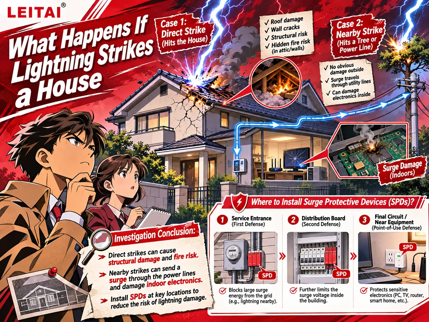
- Some small installations with low exposure. A home or small store that is connected underground and has no external lightning protection can contain a single Type 2 SPD at the main panel plus protection at the end use of valuable equipment. The sizing approach for a 200 A residential service walks through that case.
- Buildings exposed to partial lightning current. An external LPS, an overhead supply or a high-risk location calls for Type 1 or Type 1+2 at the origin. If you are unsure whether your SPD should be dealing with lightning at all, start with whether a surge protector protects against lightning.
- Large or sensitive installations. Remote feeder cabinets, long cables, data systems, and control apparatus require the use of Type 2 at the distribution panels and Type 3 device, or combined type 2+3 at the load points.The right number of stages is the least number of stages that ensure an effective distance protection for all critical loads of the coordinated SPD.
IEC 61643-11 vs UL 1449: Are SPD Types Defined the Same Way?
Not exactly and the readers located in the US should take care to look carefully into their comparison of catalogs. The standard IEC 61643-11, which was revised in its second edition in 2025 and read together with the general requirements already contained in IEC 61643-01, describes the subclasses according to the testing classes of a device. The UL 1449, in its turn, describes the types of devices mainly according to the location of their installation relative to the power equipment.
| Aspect | IEC 61643-11 | UL 1449 |
|---|---|---|
| Type 1 | Tested with 10/350 μs current (Iimp) | Permanently connected, may be installed on the line side of the service disconnect |
| Type 2 | Tested with 8/20 μs current (In, Imax) | Permanently connected, load side of the service overcurrent device |
| Type 3 | Tested with the combination wave (Uoc) | Point of utilization, at least 10 m (30 ft) of conductor from the service panel |
| Lightning current test | Required for Type 1 | No 10/350 μs test; Type 1 In is tested at 10 or 20 kA (8/20 μs) |
A practical outcome of this is that a UL Type 1 does not automatically mean an IEC Type 1, and vice versa. In the US, NEC Article 242 pertains to installation procedures, while NEC 230.67 stipulates that a Type 1 or Type 2 SPD must appear at services providing electrical power to any residential unit. If lightning current capability is required in the project, please insist on 10/350 μs Iimp test data as applicable regardless of the type of label affixed on the technology provider.
How to Choose a Coordinated SPD System
Please proceed through these seven tests in the specified sequence. The majority of projects go through the first four checks; the final three verify that the design will be executed properly.
1. Lightning exposure and outside LPS. Does part of the current from lightning hit the installation? If it does, go for Type 1 or Type 1+2 depending on the selected level of the lightning protection.
2. Supply voltage and earthing scheme. Based on whether it is TN-S, TN-C-S, TT, or IT, different types of protection methods should be used, as well as different levels of Uc.
3. Select Uc to be higher than the highest nominal voltage that an electrical device will be able to face, including temporary overvoltages.
4. Position of the installation and type of SPD. Trace every switchboard and every critical load for cable length; everything that is more than 10 meters away from the nearest SPD should be eligible to go through the next stage.
Iimp, In, Imax, and Up ratings. Compare similar elements with each other: Iimp with Iimp, In with In. After that, compare Up with the device at that location.
5. Impulse withstand voltage of the equipment (Uw). Verify that Up,f, which includes the voltage drop in the lead, is lower than Uw and that there is a safety factor for the most sensitive load that is protected at that stage.
6. Coordination of energies SPD to SPD. Ensure that the devices are using tested coordination data from one of the manufacturers and that you follow any separation distance mentioned.
7. Short-circuit rating and back-up protection. The short circuit current rating (ISCCR) of the SPD equals prospective fault currents at the terminals and the corresponding safety fuse or SPD disconnector must be specified.
A good kA number from one single datasheet does not answer any of the seven checks on its own.
Frequently Asked Questions
What is the difference between SPD Type 1, 2 and 3?
Type 1 is subjected to a 10/350 μs lightning impulse test at the point of installation, while Type 2 undergoes an 8/20 μs lightning impulse test designed for the purpose of evaluating the distribution boards with regard to induced and switching surges. The test utilized for Type 3 involves the combination wave test, which reflects the final voltage limitation that protects the sensitive equipment. The listed types denote various functions in place of different qualities.
Do I need Type 1, Type 2 and Type 3 SPDs together?
Only when installing all three types is necessary. Type 1 is used for locations where partial lightning currents flow, Type 2 is used in the distribution board, and Type 3 is for locations with sensitive equipment that are more than 10 m away from the nearest Type 2. Many small installations need only one or two types.
Can a Type 1 SPD replace a Type 2 SPD?
Although a Type 1 can be fitted in a location suitable for a Type 2 device, it is not often used instead. Typically, spark-gap Type 1 equipment has a higher Up value than Type 2 devices, and one device alone is not able to secure devices at a distance from it. A combined Type 1+2 device is capable of performing both roles in one location.
What is the difference between Iimp, In and Imax?
Iimp is the current that the Type 1 SPD lets go of during the 10/350 μs waveform. In refers to the 8/20 μs current, which the Type 2 SPD can withstand multiple times during the operating duty test. Imax represents the maximum 8/20 μs current that a type 2 SPD can withstand once. Because of the differences between the waveforms, Iimp cannot be compared directly with In or Imax.
Do Type 1 and Type 2 SPDs need 10 metres between them?
Not as a rule. Some spark-gap and varistor pair requires distance or decoupling inductor to coordinate; older handbooks provided length of approximately 10 meters. Many newer coordinated design and Type 1+2 conjunctions do not require distance. Use coordination data from the manufacturer of your pair.
Is a Type 1+2 SPD better than separate Type 1 and Type 2 devices?
It is internally better coordinated and more compact, thus making Type 2 a very reasonable option for congested main boards. Individual components can be changed separately and allow the Type 2 to be placed on a different board. However, none of these options provide protection for devices beyond their effective distance, which means that remote loads will still need their own stage.
References
- IEC 61643-11:2025, Low-voltage surge protective devices, Part 11: SPDs connected to AC low-voltage power systems
- Schneider Electric, Coordination of Surge Protective Devices
- Electrical Installation Guide, The Surge Protection Device (SPD)
- UL Standards & Engagement, UL 1449 Surge Protective Devices
- NFPA 70, National Electrical Code, Article 242 and Section 230.67
Conclusion
When looking at SPD Type 1 2 3, one needs to understand that these are three positions on one ladder, rather than three products competing against each other in terms of kA. While the first type will survive the lightning current at the source, the second type will limit the flow and the induction along the path, and the third type will keep the voltage low where the sensitive equipment is located. Choose the dimensions of every stage based on its waveform, compare Up with the withstand voltage of the equipment, keep the leads short, and apply stages that were tested for coordination by the manufacturer.