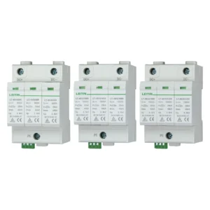

The story of Benjamin Franklin inventing the lightning rod by flying a kite during a thunderstorm is one that most of us have heard since childhood. It is also frequently cited as the earliest precursor to the modern surge protector. In reality, while lightning rods and surge protectors share the same underlying physical principles, they are distinct protective devices that serve entirely different functions. This article explores the history and evolution of the surge protector—an electrical device that has become an integral part of our daily lives.
Lightning protection has evolved over the last century, from open air gaps in the early electrical transmission lines to electrolytic and silicon carbide arresters to zinc oxide-based systems which provide protection for electrical systems and electronics nowadays. Lightning rods and SPDs serve different functions; however, they can be used at the same time.
Before Surge Protectors: Lightning Rod and Benjamin Franklin
Benjamin Franklin’s “kite experiment” is the most familiar starting point for anyone learning about lightning protection technology. According to the Franklin Institute, Franklin had already conceived the concept of a “grounded lightning rod” as early as 1750—well before his famous kite experiment in 1752. The kite experiment was intended to investigate the nature of lightning as a natural electrical discharge, while the lightning rod provided a means to protect buildings.
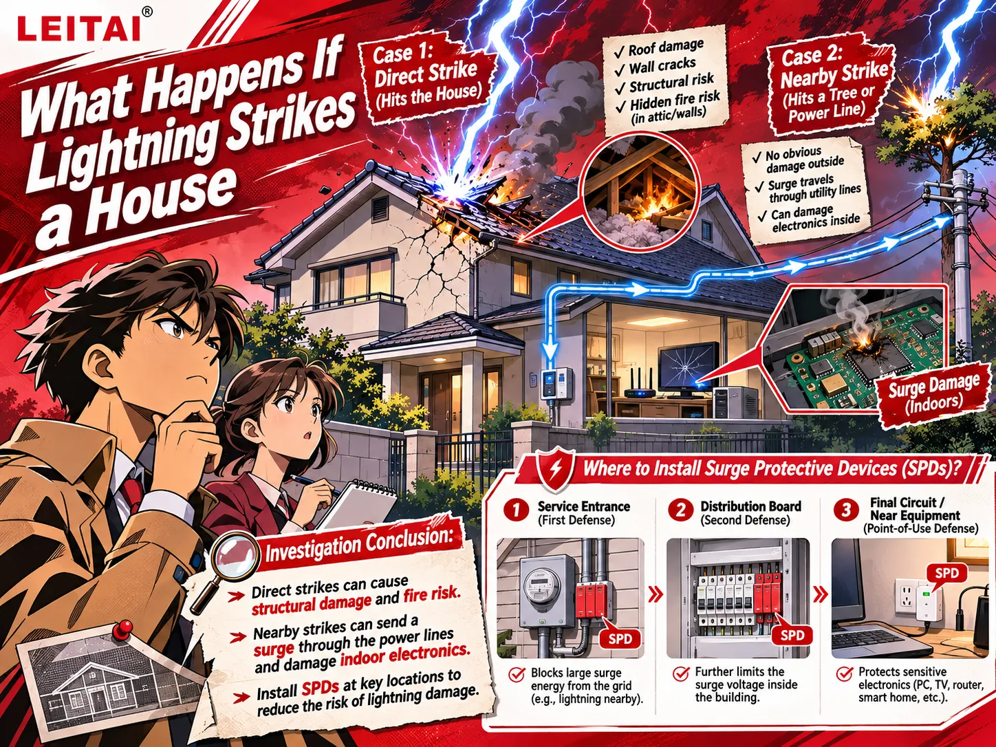
A lightning rod is part of an external lightning protection system, offering a predetermined path for lightning current to be discharged into the ground. A surge protective device (SPD), by contrast, is connected to indoor electrical equipment and serves to limit transient voltages between the conductors it protects. The two serve distinct functions and cannot replace one another; depending on how they are installed, they work together to form a coordinated protection system.
As telegraph lines—and later, electrical power networks—became more widespread, engineers encountered a new problem: transient voltages could travel along wires and penetrate the interior of equipment. Protecting the building structure alone was no longer sufficient to address this challenge.
Late 19th Century: Horn-Gap Arresters
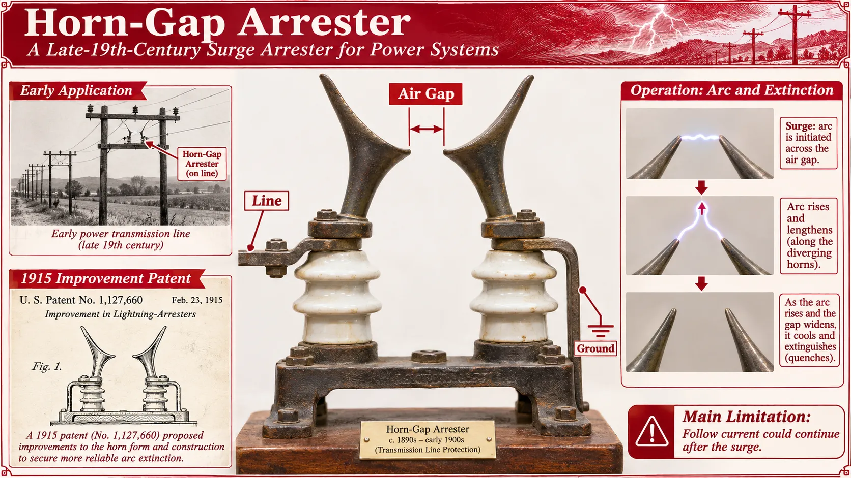
Among the early devices developed to protect electrical circuits was a simple gap-based design known as “horn gaps.” These consisted merely of two specially shaped metal rods (the “horns”) mounted on an insulating base. Lacking any complex electronic components or chemical valve elements, they were extremely inexpensive to manufacture and install. Their operating principle was as follows: when a high-voltage surge caused the air gap at the narrowest point (the bottom) to break down, an electric arc was formed. The heat from the arc—combined with the magnetic force exerted by the arc current itself—pushed the arc upward along the diverging “horns.” As the gap widened, the arc was progressively elongated and cooled until it eventually extinguished itself. These devices can be considered the earliest form of surge protection.
However, they suffered from a significant issue known as “follow current.” As noted in the bottom-right section of the accompanying illustration, even after the transient surge had passed, the normal operating voltage of the power grid would sustain the arc. The process of the arc rising, elongating, and finally extinguishing could take tens of milliseconds or longer. During this interval, the line was effectively short-circuited to the ground, which frequently triggered circuit breakers at substations, leading to power outages.
Furthermore, these devices were highly sensitive to environmental conditions; factors such as air pressure, humidity, dust, precipitation, or even the flight of an insect could alter the breakdown threshold. Additionally, the arcing process would discharge superheated ionized gas and metallic vapor, while also generating intense radio-frequency interference—all of which imposed strict requirements on the environments in which they could be deployed.
1900s-1920s: Aluminum, oxide film and pellet arrestors
The next step made by engineers was looking for a material that was conducting during overvoltage and suppressing the current following the surge. The aluminum electrolytic arrestor made use of aluminum plates and the electrolyte. The aluminum hydroxide film had high resistance and could be melted under the right level of voltage.
These devices were not developed in the 1920s but started being created in the 1900s. They had to be maintained with respect to their liquid and film condition; some configurations involved the series gap, so operation included maintenance procedure as part of protection.
Oxide film and pellet designs were another way to go. The oxide-coated pellet design was patented in 1915 followed by the improvements on lead oxide pellets in the 1920s. The pellets were able to provide the nonlinear route for the current, often in connection with the series gap. These designs led to limiting the maintenance required for the liquid cells, but their film was destructed by discharges.1910s–1930s: Expulsion-based Arresters
The expulsion arrester does not utilize the same mechanism as other arrests and employs a gas blast to extinguish the arc. Early forms of expulsion arresters originated in 1918 and remained popular during subsequent decades.
The working of newer designs hinges on an arc generated in a tube resulting in the tube releasing gas. The flow of gas cools and expands the arc and results in a timely interruption of electricity, approximately at the moment of current zero. All in all, the use of expulsion arresters was quite widespread in outdoor power distribution systems.
However, expulsion arresters have their drawbacks. Their operation may produce gas and sound, and the tube will erode over time. Replacement and operation will differ depending on a design of an expulsion arrester and an expulsion technology as a whole.
1926 Onwards: The Silicon Carbide Valve Arrester
A milestone has occurred in 1926 when John Robert McFarlin filed a patent for silicon carbide material in an arrester device. In 1930 he received a patent on a silicon carbide valve arresters that became a widespread technology in power systems in the following decades.
Silicon carbide is characterized by non-linear voltage-current characteristics: during high-voltage surge, silicon carbide may allow passing greater current than at lower voltages. Immediately after a surge, the silicon carbide limits power frequency follow current that is why series spark gaps interrupt the arc.Another important role of the series gaps was to separate the SiC material from the normal operating voltage. In the absence of gaps, the uninterrupted current could generate excessive heat. There were issues related to conduction and sparkover that gaps resolved. Regardless, SiC arresters have been used in power networks for several decades, and some operate to this day.
1968 to the 1980s: The Zinc Oxide Revolution in Surge Protection Technology
In 1968, Panasonic (then Matsushita Electric) invented a zinc oxide varistor suitable for practical applications. Metal-oxide varistors (MOVs) exhibit extremely low current flow at normal voltage levels, but the current passing through them increases rapidly as the voltage rises.
This enhanced non-linear characteristic made it possible to manufacture metal-oxide surge arresters for power systems that do not require series gaps—a component commonly used in traditional silicon-carbide valve-type arresters. Due to the nature of this non-linear curve, a small amount of current still flows even at normal operating voltages; therefore, the term “gapless” does not imply that the device is completely non-conductive in an electrical sense.
Applying these compact components to high-voltage power surge arresters required further engineering solutions. Meidensha collaborated with Panasonic to facilitate their use in power systems, and in 1975, the technology was deployed in a 66 kV power system for the first time. By the late 1970s, high-voltage metal-oxide surge arresters had come into widespread use, and by 1980, the technology had entered a new stage of development. There are varying perspectives within the industry regarding the definition of key milestones, as the processes of material research and development, field application, and the commercialization of surge protective devices (SPDs) did not occur simultaneously.
Modern SPDs: Protection for Power and Electronics
Currently, MOVs (Metal-Oxide Varistors) are widely used in a variety of equipment, ranging from power distribution systems to plug-in surge protectors. Other technologies, such as gas discharge tubes and transient voltage suppression (TVS) diodes, are also employed. Each innovation from this historical evolution remains in use today, playing a vital role in our electrical infrastructure and daily lives.
It is important to note that because an MOV is a consumable component subject to gradual aging—with each surge event causing a slight degradation in performance—traditional mechanical status indicators (which typically only change color when a thermal disconnect is fully triggered) serve merely as a binary signal that the device has failed completely. They cannot provide a real-time, quantitative assessment of the component’s remaining surge-handling lifespan. Consequently, in regions prone to frequent thunderstorms or at critical power supply nodes, utility personnel conduct regular inspections. Furthermore, electrical infrastructure projects incorporate multi-stage, coordinated surge protection systems to ensure that power generation equipment remains operational and stable, even during extreme weather conditions.
How LEITAI Products Fit Today’s Surge Protection Applications
Today, surge protective devices (SPDs) have evolved from simple, rudimentary shunt components into modular electronic units that integrate both electrical and communication functions. Yet, the core issues they address remain the same:
1. Where might a surge enter the system?
2. Which equipment requires protection?
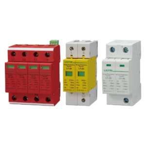
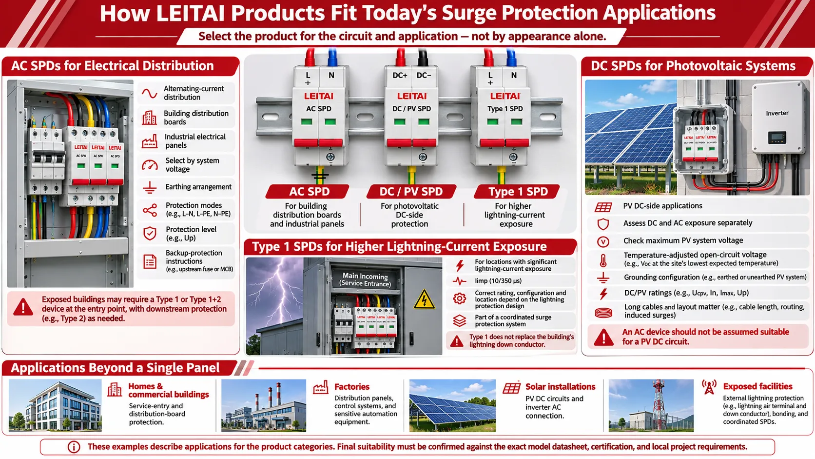
LEITAI’s product range includes AC surge protective devices (SPDs), DC surge protective devices, and Type 1 SPDs. When selecting a product, the decision should be based on the specific circuit and application scenario, rather than the device’s physical appearance.
AC SPDs for Electrical Distribution
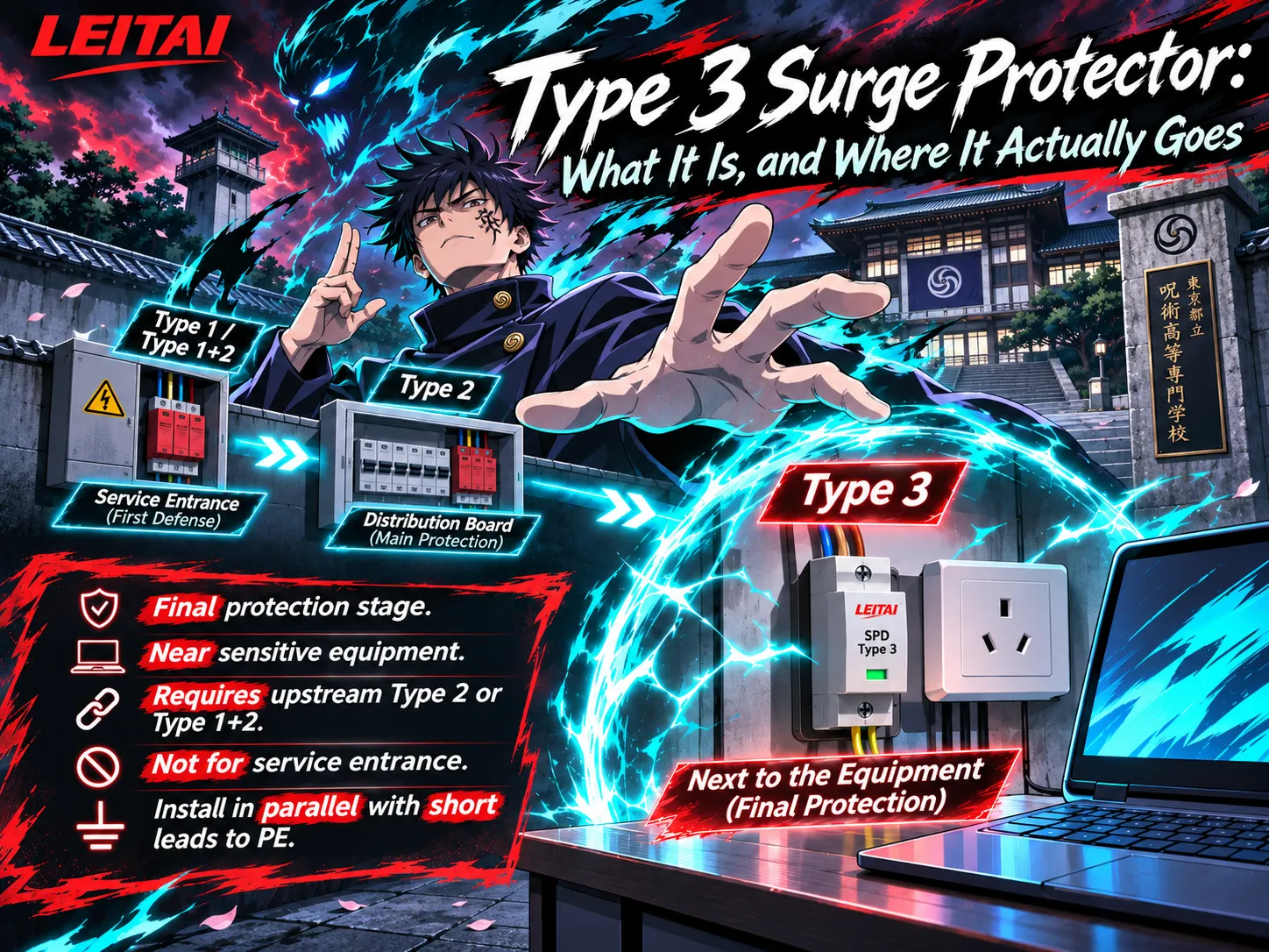
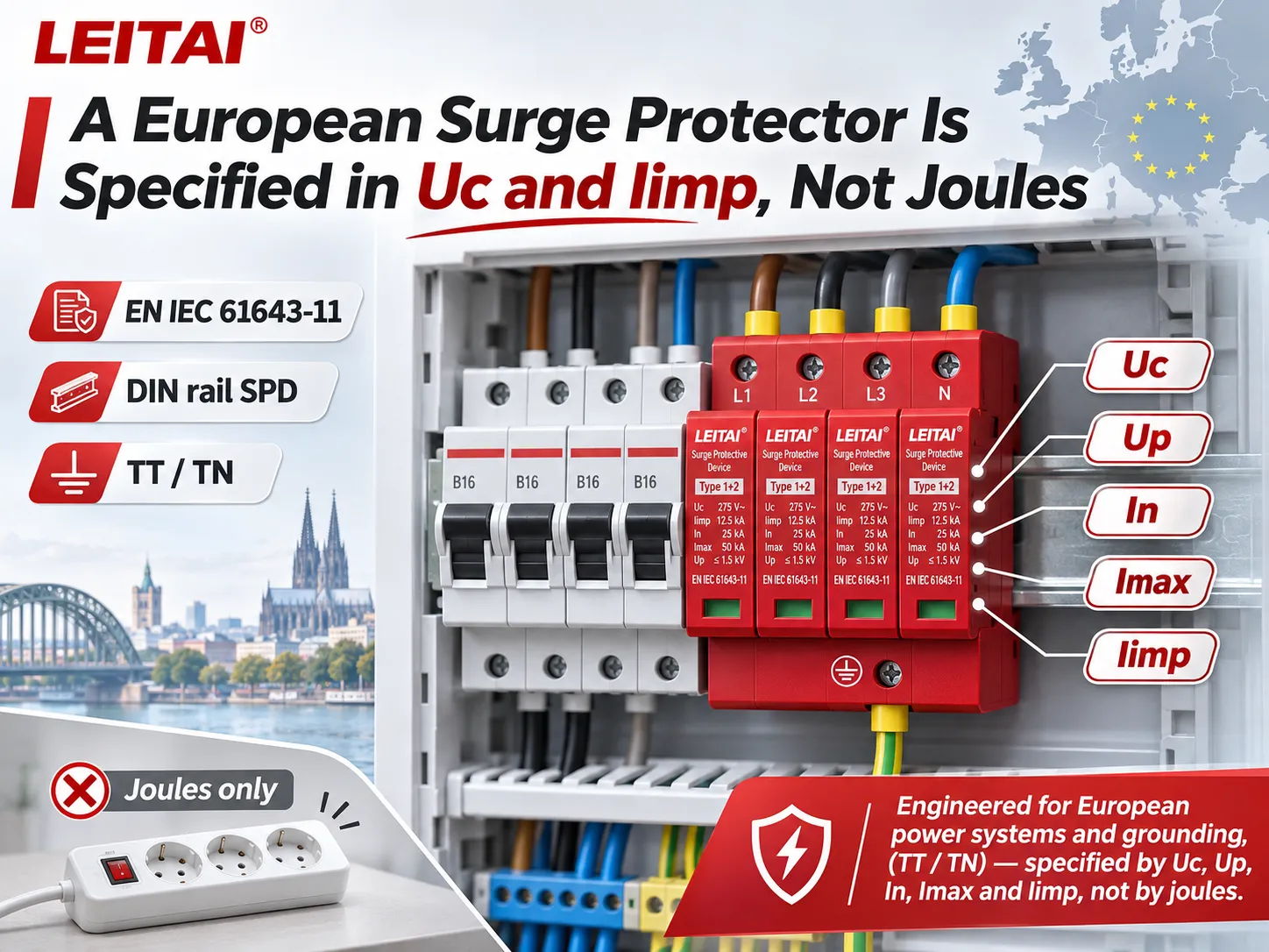
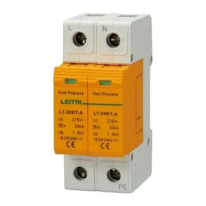
LEITAI AC surge protective devices are aimed at delivering surge protection in electrical systems using alternating current. All the criteria of selecting and using them are based on such factors as power supply voltage, the type of earthing, mode of protection, level of protection, and the recommendations made by the manufacturer concerning installation and emergency protection. When designing lightning protection systems or installations, it is advisable to use devices of Type 1 or a combination of Types 1 and 2. In certain cases, the use of downstream protection devices is advisable depending on the design of the system and applicable regulations.
DC SPDs for Photovoltaic Systems
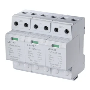
LEITAI DC surge protective devices are designed for use in DC applications of various types, including solar photovoltaic systems with DC and AC equal opportunities in terms of electricity flows. In such a case, there are various criteria about PV systems to be taken into consideration including maximum voltage of PV installation, maximum parameters of open circuit voltage, type of grounding, and SPD DC/PV ratings and voltage parameters.
Type 1 SPDs for Higher Lightning-Current Exposure
LEITAI Type 1 SPDs belong to the devices associated with the critical part of lightning current according to the IEC definition of Iimp impulse current. The choice of ratings, parameters, and positioning depends on the type of lightning protection and the requirements set by various standards.
The fact that LEITAI devices belong to Type 1 does not mean that they are down conductors of the lightning protection system in a building, but they are designed to protect electrical installations exceeding certain parameters.
Application Areas of Such Devices
Households and offices: service entrance, distribution board, and additional point-of-use devices if necessary.
Industrial plants: main distribution boards, control systems, and sensitive automation equipment.
Power stations: analysis of lightning protection of PV devices.
Outdoor installations: coordination of outer lightning protection system and other SPDs meeting necessary standards.
These are the main possible areas of application of the devices being described above.
Frequently Asked Questions
When were surge protectors invented?
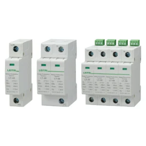
The earliest form of surge protector—the horn-gap arrester—emerged in the late 19th century. It was used on overhead transmission lines to prevent lightning strikes from damaging equipment insulation and causing power outages. The 1920s saw the introduction of aluminum-cell arresters, oxide-film arresters, and pellet-type arresters. Tubular (expulsion-type) arresters appeared in the 1930s, followed by silicon carbide arresters in the 1950s, and metal-oxide surge arresters in the 1970s. Modern high-voltage surge protectors are designed to limit overvoltages in power systems caused not only by lightning but also by system switching operations. Since 1992, the most common surge protection configurations have become the pluggable, 35mm DIN-rail-mounted SPD modules (pioneered by Germany and France) and integrated, enclosure-based power surge protection units (favored in the United States and the United Kingdom).
How do you tell how old your surge protector is?
Look for the manufacturing date or date code on the label, packaging, or installation records. In case only the serial number appears, contact the manufacturer to find out what their model code means because there is no standard format. The installation date may be more recent than the manufacturing date. If it is a panel-mounted unit, you should ask a qualified person to check it while the live covers remain unobstructed.
When did surge protection become mandatory?
There is no universal date for this. In the USA, Section 230.67 of the National Electrical Code, as amended in 2020, stipulated the requirement for surge protective devices in service supplying houses, under certain conditions including replacement of service equipment. In 2023, the list of occupancy types was extended. Enforceable provisions will depend on local applicability and the specific version of the regulation in use.
Is it true that surge protectors only last 5 years?
Actually, a five-year service term is not a standard for all types of SPDs and does not work for every case. The amount of exposure, surge force and frequency, conditions of the system, the design of the product and its installation influence the performance that the SPD is able to deliver. It is necessary to stick to the recommendations of the manufacturer when it comes to inspection and replacement of the device.
References
- The Franklin Institute — Franklin’s Lightning Rod
- US Patent 1,151,726 — Horn-Gap Lightning Arrester
- Jonathan Woodworth — History of Arresters on Power Systems, 1890–1930
- US Patent 1,763,667 — Lightning Arrester and Method of Making the Same
- Panasonic — 1968: Zinc Oxide Varistor ZNR
- Engineering and Technology History Wiki — Birth of the Gapless Metal Oxide Surge Arrester
- IEEE Power & Energy — Lightning Protection of Distribution Power Systems
- Leviton — NEC Code Requirements for Surge Protection
- Schneider Electric — Life Expectancy of Surge Protective Devices
Conclusion
The history of surge protection is a story of solving successive problems: creating a discharge path, interrupting follow current, improving voltage-limiting performance and bringing protection closer to sensitive equipment. Modern SPDs build on that history, but effective protection still depends on selecting the right device and integrating it into the electrical installation.