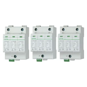

A DC surge protective device (SPD) designed for solar applications should not be confused with an AC panel protection device that has been simply labeled differently. The DC side of a solar array is always powered, and such systems generate the highest voltage in cold conditions. With regards to current, it behaves differently than in AC circuitry. Therefore, to select the SPD for the installation, it is best to consider the maximum DC voltage possible, rather than just the value stated on the inverter: 1000 V or 1500 V.
In a nutshell, the Ucpv indicating the maximum voltage should be set at levels higher than the open-circuit voltage produced in cold conditions. A type 2 solar SPD is sufficient for use at a combiner box or at a DC input of the inverter while the installation can expect no partial lightning currents. Only if the array has been equipped with a lightning protection system and separation distance is not maintained, type 1+2 SPD should be considered. An AC SPD that has passed only IEC 61643-11 tests cannot be applied in DC systems, since an appropriate device should be developed according to IEC 61643-31 standards.
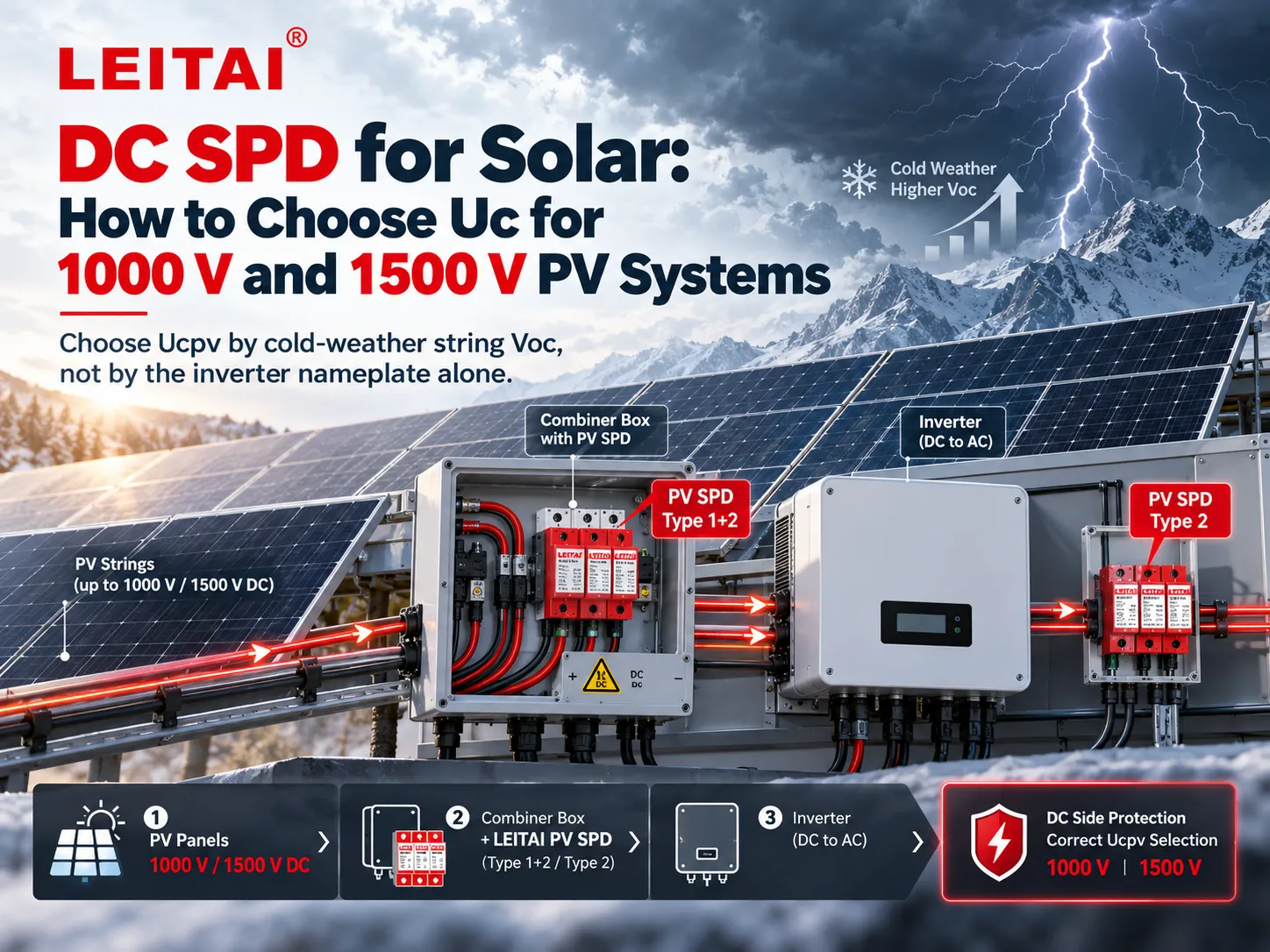
The Short Version for a Solar DC String
First, determine the open-circuit voltage of the string at the site’s lowest temperature. Order a DC SPD with a Ucpv greater than that voltage, factoring enough margin that a cold morning or incident irradiance over the standard test conditions will not cause the varistor to go into a continuous conduction mode. In the Lead AI catalogue, DC SPD voltages available are 600 V, 100 V, 1500 V, and 2000 V.
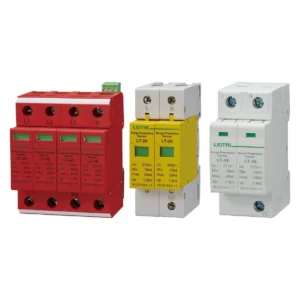
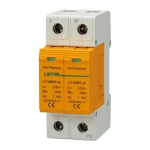
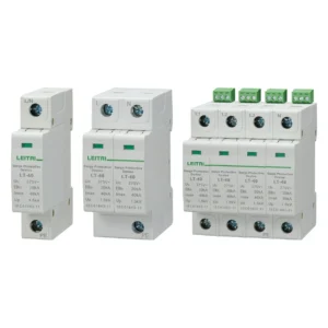
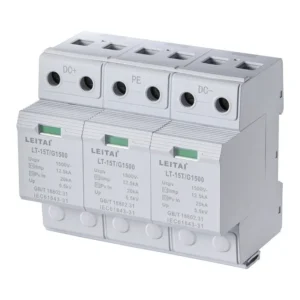
A Type 2 surge protection device (SPD) such as the LT-40 series is recommended to protect against induced and switching surges at the combiner or input to the inverter. If there is hreat to the DC wires from lightning, a Type 1 + 2 SPD, for example, the LT-15T should be installed instead. It is also required that the length of the interconnect leads be as short as possible and that the protective earth is bonded in the correct way. There should also be an AC SPD at the output of the inverter, since the DC SPD does not provide such protection on this side.
Why the DC Side of Solar Is a Different Problem
We define a PV string as a collection of long conductors that exist outside. Both lightning strikes nearby and the switching of the AC supply produce some voltage in the conductors. Since the inverter input is sensitive, a failed DC input implies a blackout instead of a reset circuit breaker.
What makes this different from the home AC panel is three facts:
(1) Anytime there is light, the voltage is there. Thus, the SPD must sustain that voltage at all time instead of during surges only.
(2) The voltage of the module grows as the temperature of the cell decreases. So the string that is well within the class at 25 °C may be almost at its limit at the dawn of winter.
(3) When the current reaches zero, DC arcs don’t extinguish themselves. That is what the thermal device and the PV short-circuit designation are for. In other words, a device for AC is not made for that purpose.
What IEC 61643-31 Actually Requires
IEC 61643-31 describes surge protective devices for the DC side of photovoltaic system installations. IEC 61643-32 covers the criteria for choosing and using the devices. Array design principles, including how to determine the maximum voltage, are covered in IEC 62548 and in the relevant electrical code. No document uses the term “1000 V system” in a way that permits calculations to be ignored.
The continuous operating voltage is referred to as Ucpv on a PV equipment data sheet. Ucpv is defined to be the maximum DC voltage that the SPD can handle continuously without damaging the device. The selection principle is simple to articulate but easy to mess up in practice: Ucpv must be equal to or greater than the maximum open-circuit voltage that may be encountered at the terminals of the SPD.
This maximum is the value measured during low temperature operation, not the STC rating:
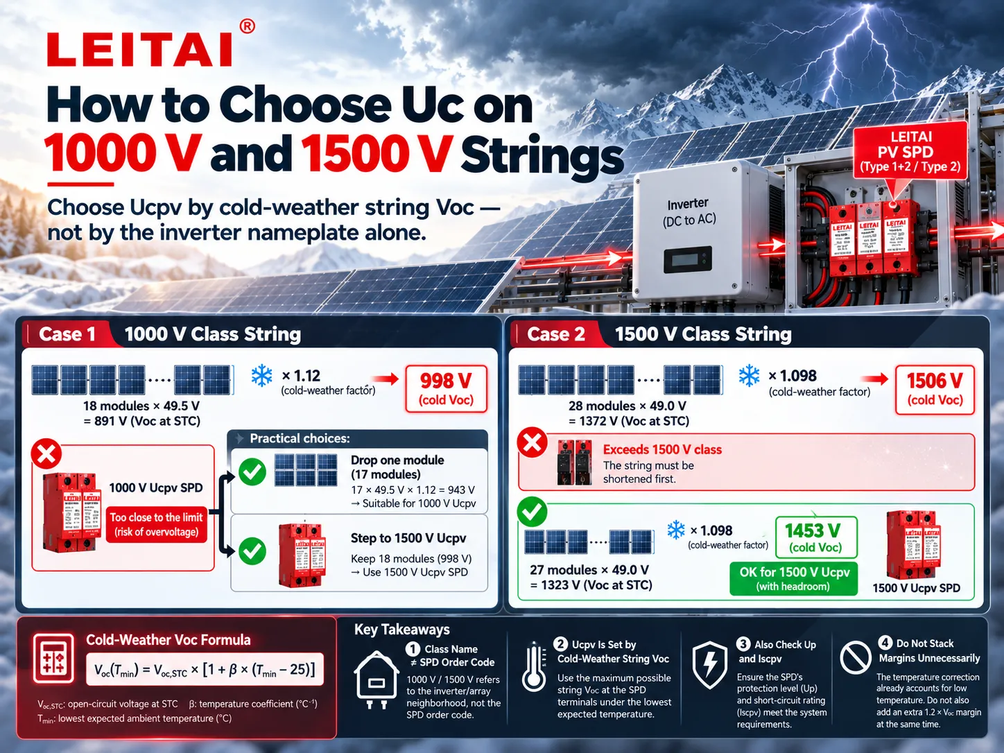
Voc(Tmin) = Voc,STC × [ 1 + β × (Tmin − 25) ]
Voc,STC is the string open-circuit voltage at 25 degrees Celsius. β is the coefficient for the change in Voc with temperature and is always a negative number, generally in the range of -0.25% to -0.35% per degree Celsius for crystalline silicon. Tmin is the lowest cell temperature that one is designing for. Because β is negative, a lower Tmin results in a larger Voc value.
Some practitioners use a more simplistic method of determining Ucpv, by stating that it should be equal to or greater than 1.2 Voc,STC. This gives users some margin for low temperature operation. Note that 1.2 should not be applied on top of a temperature-corrected value of Voc; otherwise, one expands the operating voltage range unnecessarily and creates a need for a 1500 V SPD instead of a 1000 V one and then a 2000 V SPD instead of a 1500 V one, without need.
In addition to Uc value, one has to check two more criteria. The voltage protection level must be lower than impulse withstand ratings of all the equipment on the DC line. One also needs to confirm that PV short-circuit withstand capability of the SPD interpreted as Iscpv rating is at least equal to the potential short-circuit current of the system at the point of installation.
Type 2 and Type 1+2 in Plain Terms
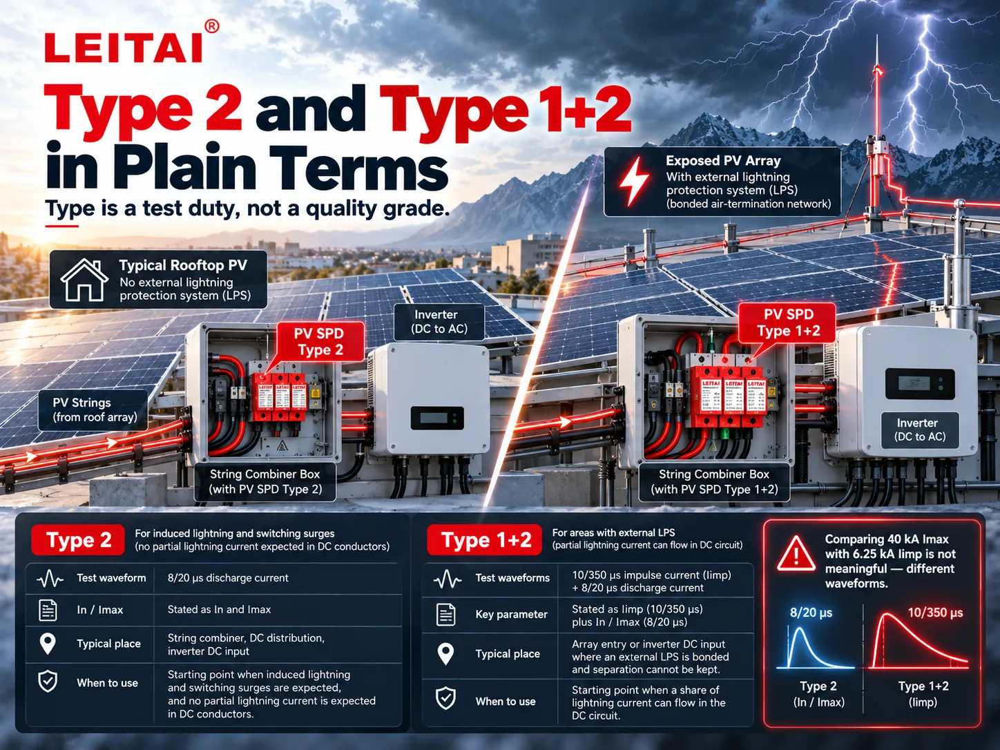
Type is a test duty, not a quality grade. The same distinction used on AC systems applies on the DC side of solar, with the product standard changed to IEC 61643-31.
| Duty | What it is tested for | Typical place on a PV system | When it is the starting point |
|---|---|---|---|
| Type 2 | 8/20 µs discharge current, stated as In and Imax | String combiner, DC distribution, inverter DC input | Induced lightning and switching surges, no partial lightning current in the DC conductors |
| Type 1+2 | 10/350 µs impulse current, Iimp, plus the 8/20 µs test | Array entry or inverter DC input where an external LPS is bonded and separation cannot be kept | A share of lightning current can flow in the DC circuit |
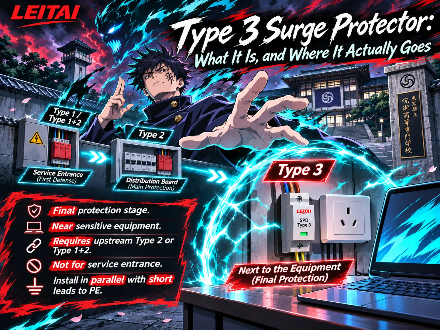
| Type 3 | Combination wave, close to the equipment | Sensitive DC controls, only behind an upstream PV SPD | Never as the only device on the array |
Generally, a rooftop setup without any external lightning defense system is classified as a Type 2 installation type. As for a ground-mounted plant and a roof structure that has the installation of an air termination system connected with the frame of the installation, such installations require a project-based assessment of the clearance. When it becomes impossible to provide for such a clearance, the partial lightning current becomes a design solution and thus a PV SPD Type 1 + 2 needs to be used. One more comparison of 40 kA Imax with 6.25 kA Iimp is not sensible as we are speaking about different sorts of electric waves.
How to Choose Uc on a 1000 V String
An inverter rated at 1000 V does not imply that it requires a Ucpv of 1000 V. It simply indicates that we are in the area of the specified voltage.
We use a string of 18 crystalline modules in series with Voc of 49.5 V each under the STC conditions. This means that the string Voc,STC is calculated as 18 × 49.5 = 891 V. In order to calculate the cold open-circuit voltage, we apply the following parameters: β = −0.30 %/°C, temperature of cells at −15 °C, and the temperature rise factor is calculated as 1 + 0.003 × 40 = 1.12. We find that the cold open-circuit voltage equals 891 × 1.12 = 998 V.
When we consider a DC SPD with Ucpv marked at 1000 V, we see that it is only around 2 V higher than what we calculated. This does not allow for any margin. In case of the irradiance above 1000 W/m², if a slightly steeper module coefficient is evident or a colder hour is there, we end up with SPD rating reached or surpassed, leading to conduction of varistors in normal operation conditions and heating them in the process. One of the solutions is removing one of the modules, and it would lead to the voltage equal to 17 × 49.5 × 1.12 = 942 V, leading to the voltage that is safely under 1000 V. The other choice is the next catalogue voltage of 1500 V Ucpv.
Thus, if Ucpv is upgraded to 1500 V, it does not make the system voltage higher than 1000 V; the string is still considered to be a 1000 V leader. What changes is the device’s ability to be there without conducting. Study it closely. Higher Ucpv allowing for much higher Up can work worse for the inverter despite being safer for the SPD.
The 1.2 shortcut applied to the same string shows us how the voltage reaches 1.2 × 891 = 1069 V, giving us the same result: no order can be placed for the 1000 V model. However, it also does not allow ordering the 2000 V one.
How to Choose Uc on a 1500 V String
The principles of arithmetic still apply, but the stakes are higher because every other DC component must have a voltage rating of 1500 V or higher.
Now if we consider 28 PV modules of 49.0 V each, the equivalent string voltage should be 1372 V at STC. Given the value of β (the temperature effect) as -0.28 %/°C and Tmin = -10 °C, the voltage adjustment factor becomes (1+0.0028 * 35 = 1.098). Thus, the voltage should be 1372 * 1.098 = 1506 V at cooler temperature conditions (cold voltage). The new updated voltage goes above the 1500 V Ucpv mark and exceeds the equipment of the 1500 V class. As far as SPDs are concerned, it is not the first thing to be checked. Adjust the string until the cold Voc voltage falls within the maximum voltages for inverters (both the cables’ and the isolators’ ratings), after which Ucpv can be selected.
Let us decrease the number of modules from 28 to 27: 27 * 49.0 = 1323 V for the STC case, and 1323 * 1.098 = 1453 V for the cold case. In this case, the 1500 V Ucpv unit has about 47 V of space remaining. Although this is possible given the temperature assumption, it relies on the fact that the site is not colder than -10 °C and that the module data sheet matches the β value used. If the project requires the 1.2 x Voc screen, it can be calculated as (1.2 x 1323 = 1588 V), and thus the 1500 V equipment fails this requirement, and the next step would involve checking the 2000 V systems instead of going through windowing of every voltage component in the circuit.
| Decision | 1000 V class string | 1500 V class string |
|---|---|---|
| What the class name means | The inverter and array neighbourhood, not the SPD order code | The same |
| Number that sets Ucpv | Cold-weather string Voc at the SPD terminals | The same |
| Catalogue step that usually fits | 1000 V only with real margin; otherwise 1500 V | 1500 V only with real margin; otherwise 2000 V |
| Hard stop before the SPD | Inverter maximum DC input | Inverter, cable, combiner and isolator, all at 1500 V |
| What a higher Ucpv costs | Often a higher Up; check the inverter withstand | The same |
| SPD type beside the voltage | Type 2 unless lightning current can enter the DC circuit | Type 2, or Type 1+2 on an exposed plant with an LPS |
The Half Metre That Decides Performance
An SPD operates in parallel. The lead connecting the SPD must be short for the SPD to function effectively. The voltage added by the lead is proportional to the lead’s inductance times the slew rate of the surge current. In a PV system this is seen in the form of a loop: DC+ to the SPD, DC− to the SPD, earth lead back to the earth bar.
The leads must therefore be made short and direct. An SDD installation guideline is that loop leads should be limited to a total length of around 0.5 m. Half a meter of lead may lead to a higher let-through voltage than the difference of two Up values given on the datasheet. Position the DC SPD next to the terminals being protected, and avoid placing it deep in the cabinet and trying to dress the cables neatly. Do not connect the SPD in series with the string. It does not replace the DC isolator or the fuses, nor does it provide any protection to the inverter.
The pole configuration and the earthing scheme must match. A floating PV system does not have the same wiring as a single-phase AC board. The common connection is from DC+ to earth and from DC− to earth with a necessary plus-to-minus connection based on the manufacturer’s configuration. Applying AC wiring practices to a two-wire DC string often results in an installation with little or no effective protection in place.
Combiner Box, Inverter, or Both
In the case of the SPD, it should be situated between the part of the device that it needs to protect, as best demonstrated with the string inverter next to a small panel. A particular type of SPD device used at the DC input of the inverter would complete the distance voltage scheme for this inverter. However, in the field array with a long distance DC cable going back to the inverter room, installing only one device at one of the ends of the cable does not help. IEC 61643-32 specifies that you should install a coordinated PV SPDs at both ends of the long cable, which can be classified as more than 10m. One end of the cable leads to the combiner or array junction box, and the other end goes to the inverter DC input.
It is also stipulated that the two devices should be of the same voltage class and compatible with each other. For example, using a 1000V device at the combiner and a 1500V device at the inverter in the same string means that one of the devices is not suitable for use. The output AC circuit of the inverter is separate from DC and it needs dedicated AC SPD that follows IEC 61643-11 requirements but not IEC 61643-32.
Once just commissioned, the status window becomes the part of the protective measures used. When the PV has disconnected, it signals a breach of power, rather than a success. Make sure to plan the inspections along with the rest of DC maintenance and make sure to replace the cartridge or device when on the indicator not to do so after a failed inverter after the inspection of the equipment has been performed.
Where Leitai Fits
Leitai manufactures the SPD. It does not design the string layout or pull the permit. The voltage calculation above still has to be done from the module datasheet and the site temperature. With that number in hand, two published PV families cover the usual dc spd for solar choice.
The LT-40 G series is a Type 2 PV SPD for the DC side, with Ucpv steps of 600 V, 1000 V, 1500 V and 2000 V DC, In 20 kA, Imax 40 kA, a published Up of 3.0 kV and Iscpv 500 A, tested to IEC 61643-31. It is the normal device for combiner boxes and inverter DC inputs where lightning current duty is not required. Confirm Up and Iscpv on the exact voltage variant before ordering, because a single headline Up should not be assumed identical at 600 V and at 2000 V, and an array whose prospective short-circuit current is above 500 A needs a device rated for that current.
The LT-15T is a Type 1+2 PV SPD at 1000 V or 1500 V DC, with Iimp 6.25 kA on the 10/350 µs waveform, In 20 kA, Imax 40 kA and Up 3.5 kV, also under IEC 61643-31. It is the device to consider for array and inverter locations where an external lightning protection system can deliver partial lightning current into the DC circuit. It is not a reason to skip the Uc calculation. A Type 1+2 unit with the wrong Ucpv still fails in ordinary daylight.
The AC side of the same inverter is a different product. The comparison of Type 1 and Type 2 duties on AC systems is covered separately in the Type 1 versus Type 2 SPD note, and the general meaning of the three SPD types is set out in what an SPD is.
FAQ
What is a DC SPD for solar?
The DC surge-preventing device for solar power generation is known to be a protective apparatus that is fitted in the DC section of photovoltaic systems, in the position between solar panels and inverter. It minimizes transient incidences such as lightning and switching over-voltage. According to IEC 61643-31 regulation, it has to be classified as a PV device with a Ucpv rating being higher than the string’s maximum voltage as an open circuit.
How do I choose Uc for a 1000 V PV system?
First, find the value of Voc of the string at the lowest temperature in the design cell. If this value only reaches slightly below 1000 volts, do not proceed to use a 1000 volt Ucpv SPD. You should either decrease the strings until an acceptable margin is achieved or move on to a 1500 volt Ucpv model to check the value of Up for the inverter.
How do I choose Uc for a 1500 V PV system?
Use the same cold-weather Voc. If the result is higher than 1500 V, the string is too long for a 1500 V system, and only changing the SPD doesn’t solve the inverter and cables. Once cold Voc is well below 1500 V, a 1500 V Ucpv SPD is usually appropriate. If, however, a project rule specifies that 1.2 times Voc at STC is used and that figure exceeding 1500 V, then only move to a 2000 V Ucpv Type 2 unit provided that all other DC equipment is rated for the actual string voltage.
Can I use an AC SPD on a solar DC string?
No. An AC SPD is built and tested for circuits that cross zero. PV DC does not. Use a PV SPD to IEC 61643-31, with the correct Ucpv, Up and PV short-circuit rating. Keep the AC SPD on the AC output of the inverter, where it belongs.
Do I need Type 1 or Type 2 on a solar array?
Most rooftop arrays without an external lightning protection system use a Type 2 DC SPD. Where an external lightning protection system is bonded to the array and separation distance cannot be maintained, review a Type 1+2 PV SPD. Type 3 is only a final stage near sensitive electronics, behind the PV device, never the only SPD on the DC string.
References
- International Electrotechnical Commission — IEC 61643-31, requirements and tests for SPDs for photovoltaic installations
- International Electrotechnical Commission — IEC 61643-32, selection and application principles for SPDs connected to photovoltaic installations
- International Electrotechnical Commission — IEC 62548, design requirements for photovoltaic arrays
- Leitai — LT-40 G series Type 2 PV SPD, Ucpv 600 V to 2000 V DC
- Leitai — LT-15T Type 1+2 PV SPD, 1000 V and 1500 V DC
Conclusion
The cold open circuit voltage of the string, lightning current behavior, and lead length all play a significant role when selecting a solar dc spd. If the voltage of an string is 1000 V, then Uc rating of the SPD is also 1000 V only if the Voc is below the Uc ratings. If the Voc is higher than the Uc rating, then one must choose the SPD rating of Uc of 1500 V. If the string has a voltage of 1500 V, then one must choose an SPD of Uc of 1500 V and should not try to move up to improve performance. Where it is possible to do so, Type 2 must be used whenever possible for the normal combiner dc inputs; Type 1+2 must be used when the system is designed to accommodate the lightning current in it. Most of the protection presence is determined on the half-meter length of cable between the SPD unit and the fault terminal.