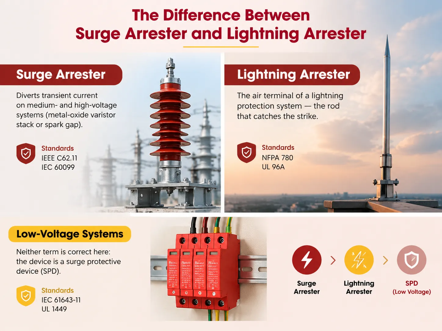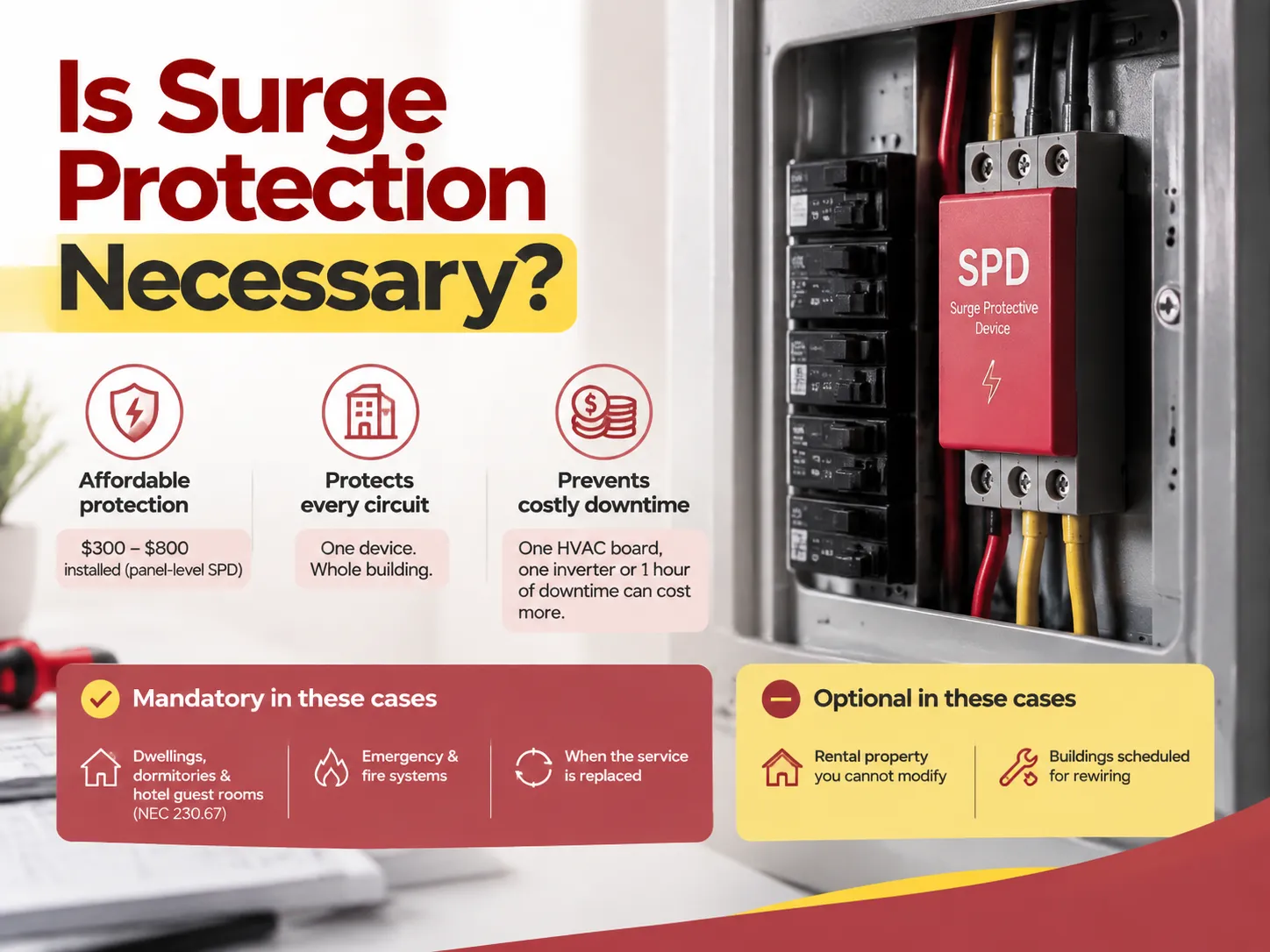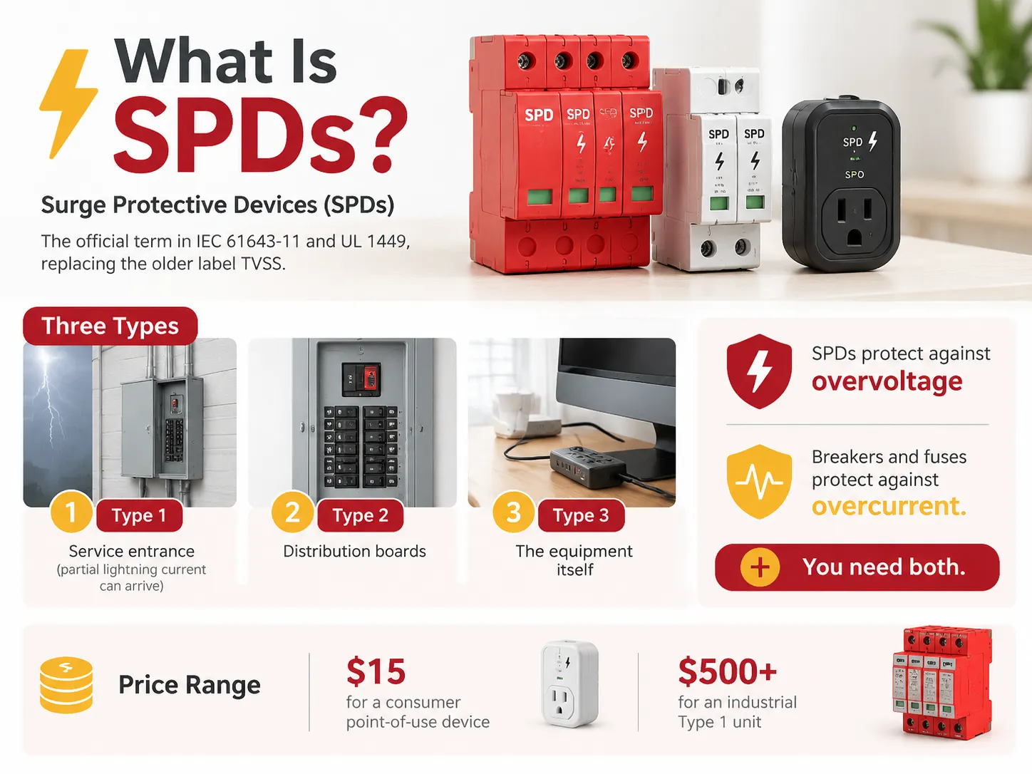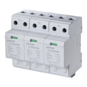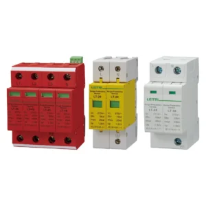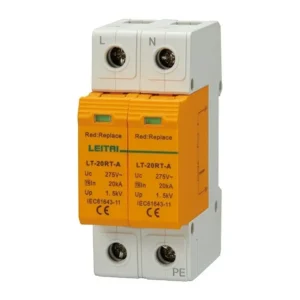

The reason behind the simplicity of the surge-protector circuit design is that the device’s working principle is parallel to the power supply. As a result, most of the connections are related to wiring methods and earthing of the surge protection device. In this case, the current moves from the busbar or circuit breaker to the surge protector and then to the main earthing bar via the earth terminal, which is connected to the grounding system in the most direct way because there is no connection in series with the load. All crucial components are situated in a few conductors instead of the device itself.
Surge protector circuit design is easy due to the working principle of the device which is parallel to the supply. Thus, the greater number of connections deals with the wiring techniques and earth connection of the surge protection device. Here, the current flows from the busbar or circuit breaker first to the surge protector and then to the main earth bar through the earth terminal that has direct wiring with the grounding system as the connection is not in series with the load. The necessary parts are located along different wires rather than within the device itself.
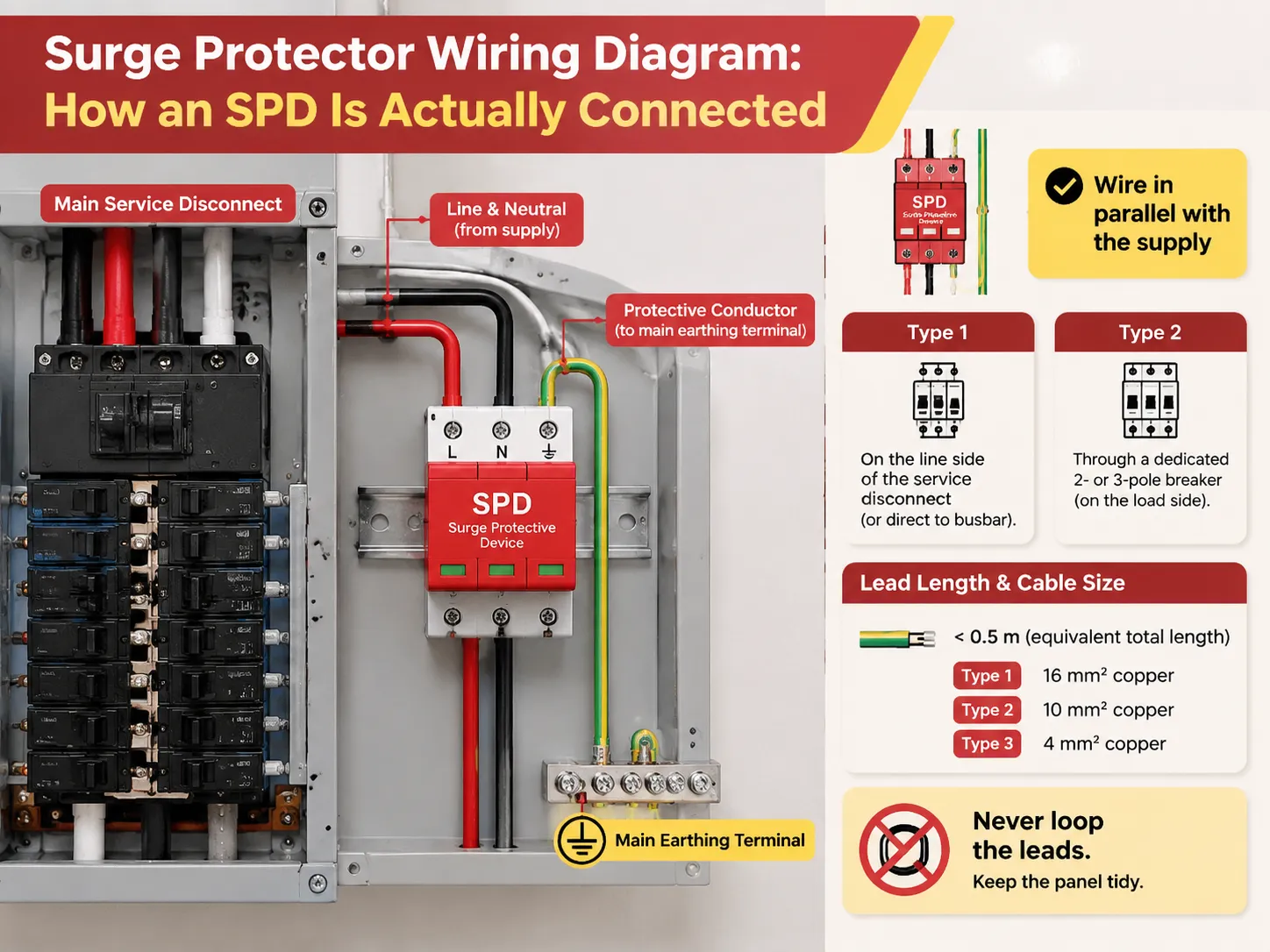
What the Diagram Actually Shows
Five aspects, in order.
- The input and the primary protective device. This aspect determines where the SPD should be connected, which dictates the functionality of the SPD.
- The SPD connections. The connections L1, L2, L3, and N feeds from either the busbars or the circuit breakers.
- The earthing system of the SPD. A separate and dedicated protective conductor must connect from the SPD to the main earthing point, not a shared conductor or a screw nearby.
- Backup protection devices. A fuse or a circuit breaker must be placed upstream of the SPD.
- The status circuit. If there is a status circuit, it must be a dry circuit that sends signals back into the monitoring circuit.
The information mentioned in the diagram depicts the absence of the load current through the SPD, series insertion, etc. The overall purpose of the SPD is to guarantee the lowest impedance for the SPD to observe what is beyond the SPD, that is, busbar from one side and the earth from the other.
One of the signs that people find challenging to comprehend upon the first encounter is the N-PE line. When used in TT systems and some TN systems, the neutral-to-earth circuit has introduced its own protective device and hence appears as a separate branch in the diagram. A combined N-PE arrester rated Iimp 7 kA or 12.5 kA on the 10/350 µs waveform handles that path with a 1.25 kV protection level and a 20 kV Uoc rating, which is what the neutral-to-earth mode demands on installations where that mode is live.
Step by Step: Wiring a Panel-Mounted SPD
The below sequence refers to a distribution board with the SPD placed on a DIN rail inside the panel, or in a stand-alone box nearby. Isolation and lock-off are a must before proceeding to any further operation because this type of panel work is classified as liv- and work-adjacent and can only be carried out by a certified electrician.
- Verify the system. Check the nominal voltage and grounding type: 230/400 V TN-S, 230/400 V TT, 120/240 V split-phase, 277/480 V wye, or delta. The mode of the SPD must match it. Some paths will be left unprotected by a delta wye device.
- Check for short-circuit capacity. Measured from the NEC 110.24-required label or from the power study, the available short-circuit current should not exceed the maximum value of the SPD for the short circuit.
- Choose the installation location based on length of cables rather than pleasing appearance. The SPD must be installed as close to the bus as possible. If there is a meter of conductor required because of lack of space, the protection rating of the SPD becomes optimistic.
- Install supplemental protection. Use either the separated breaker or fuse required by the installation guidelines, or manufacturer’s disconnecting device if SPD requires it. SPD with internal protection should follow the manual instead of being equipped with a device.
- Wiring. The power cables should be straight, parallel and as short as possible. Avoid sharp bends and crossing of cable bundling in many places, as well as crossing in the loop.
- Wiring the earth cable. It is important to select a single cable type and size correctly for the earthing.
- Hardware: Torque each termination as specified by the device and installation labels using the appropriate tools.
- Install signalling circuit if needed, afterwards name the circuit.
- After commissioning, check with the indicator showing that everything is okay. Take a picture and write down the name of the module and installation date for the next user.
When the SPD is not protected internally, the disconnection device is not an option. A damaged varistor will go short-circuiting without any device to break the follow current.Purpose-made hardware exists for exactly this: an SPD back-up disconnector with a 3 A trip current and a 30 kA Iimp rating clears the fault while preserving the SPD’s function for everything short of that failure.
Common Wiring Mistakes and What They Cost
There are some problems that frequently recur during field audits. Here is a summary of these problems, listed in order of severity.
- Long Leads. Every single meter of wiring connected to the SPD adds around 1 µH of inductance. This means around 1 kV of additional voltage when a surge occurs. If your SPD is rated at 1.2 kV and has gone through a 150 mm wire connection, it may act like 3 kV on a full meter of cable. A 1.2 kV device that is installed improperly performs worse than a 1.5 kV device that is installed correctly.
- Insufficient earth wire. The minimum size of the earth wire as per the IEC standards is 16 mm² copper for Type 1, whereas Type 2 requires a minimum of 10 mm², and Type 3 requires 4 mm². The main problem for Type 1 applications is when the installer tries to use 2.5 mm² wire as a protective earth wire. This is also the biggest threat to the efficiency of the connection.
- Connecting the SPD to the wrong earth. An easy way out would be to connect the SPD to a screw connected to the nearest building structure rather than to the main connection point for the earth wire.
- Incorrect type for the application. Examples of incorrect installation will be using Type 2 device on the load side of the circuit breaker, or using Type 3 device within 10 meters from the service point. Either of these installations is improper.
- Using an unprotected SPD. The carelessness of the installer in forgetting to install the backup device that the manufacturer requires can result in failure of the whole installation.
- Incorrect connection of the modes. If L goes to N terminal or if the N-PE device hasn’t been installed for TT system where the neutral mode is active, it means the installation is ineffective.
Another thing is to think about whether what has been on the plans matches the installation. This is especially important in the case of the panel having been modified multiple times since upgrades change the position of the busbar. A drawing that has not been updated is worse than no drawing, and if you are reusing an existing schematic for a new device, the quickest sanity check is to compare it against the manufacturer’s own surge protection product literature and selection manuals before ordering anything.
Does the Type Change the Wiring?
Indeed, in three ways.
- Connection aspect. Type 1 can be found on the line side of the service disconnect where it can get connected straight to the busbars, whereas Type 2 shows up on the load side and is generally connected with a dedicated breaker. As for Type 3, it is a device of the last stage installed at or in proximity to the equipment.
- Availing back-up protection. A big number of Type 1 devices function without the assistance of an outside overcurrent device and rely instead on the internal protection while just about most of the Type 2 devices function with the breaker or fuse indicated in the coordination chart of the producer.
- Budgets of length and cross-section. In general, the higher the type of the device the heavier the denomination of wires applied with more strict budget of lead lengths being followed.
Type 1+2 combined devices sit in the middle, with two sets of rated parameters behind one set of terminals. A combined device rated Iimp 6.25 kA at 10/350 µs and Uoc 20 kV with a 1.25 kV protection level is a typical answer for a main distribution board in a building that has a lightning protection system but limited room for two separate devices — one mounting, one set of leads, both test regimes covered.
In three-phase systems, the SPD considering modes should cover L-N, L-PE and N-PE depending on the earthing arrangement. The same physical device may exist in the form of single-phase SPD and three-phase SPD and as a device with a disconnected N-PE module. Regarding TN-S system and TT system, both wiring diagrams may look identical in the panel although the internal paths of protection are different in the two cases.
Before You Order Anything
The errors associated with electrical systems originate in miscalculations as to the ordering of devices. In order to avoid costly and embarrassing instances of sending equipment back for revision, spend five minutes on the review process to avoid unnecessary returns.
- Type based on location. Be sure to establish whether it connects upstream or downstream of the main overcurrent device, as the decision whether to choose a Type 1 or a Type 2 SPD is one based on positioning considerations that cannot be rectified later by comparing kA ratings.
- System voltage and earthing arrangement. The voltage and earthing system will be based upon whether the network is a delta or one of the other systems, but will also depend upon the exact voltage level such as 120/240 V split-phase, 208Y/120 V, 480Y/277 V or 230/400 V TN-S or TT.
- Available fault current determines the minimum required short circuit current rating, which can be determined by examining the 110.24 marker or the relevant publication and not estimated.
- Space and mounting. The required device might range from a single module to multiple devices located in separate enclosures or within the panel in a manner that does not result in any spare ways, preventing compliance with regulations.
- Over the last few years, electrical systems have proliferated in size and capability according to the ability of electrical equipment manufacturers to make improvements in their devices over this time.
Frequently Asked Questions
How is surge protection wired?
Along with the supply. The apparatus receives the line and neutral from either the busbar or a specific breaker, while a unique earthing conductor leads to the main earthing point. The SPD does not carry any load current, nor does it interrupt the supply. There are two factors dictating performance: the total lead length from the busbar to the device and to earth (which must be kept short and simple) and the cross section of the grounding conductor used.
Does a surge protector go on the line side or the load side?
The determining factor is the type rather than the personal choice. A Type 1 device is rated for installation on the line side of the service disconnect but may be used on the load side also. A Type 2 is rated for installation on the load side of the major overcurrent device in service equipment and distribution boards’ loads. A Type 3 must be installed at the load side end with at least 10 m of conductors away from the service. An installation of Type 2 instead of Type 1 is the most frequent mistake in this respect.
How do you hook up a surge protector?
To confine and immobilize, to check the voltage and earthing layout of the system, to determine the maximum fault current in comparison to the short-circuit rating of the SPD, to mount the enclosure close to the bus bar in the way the panel allows for, to install a proper back-up breaker or fuse, to connect power wires in a direct and short manner, to take a correctly sized earth cable to the main earthing terminal, to torque all connections to the specified level, to wire the status contact if applicable, and only after all these operations to carry out commissioning and make a selfie of the outcome. This work belongs to an electrician with a corresponding license, as the use of plug-and-play systems also implies dealing with active installations.
Does a surge protector need a ground wire?
Yes, and it is the most important conductor in the installation. An SPD works by diverting surge current to earth, so without a low-impedance earth path the device has nowhere to send the energy and its rated protection level becomes meaningless. The earth conductor must be dedicated, sized to the type of device, routed as directly as possible to the main earthing terminal, and never shared with a convenient local fixing. An SPD on a poor earth is a device that appears to work and does not.
References
- International Electrotechnical Commission — IEC 61643-11 and IEC 61643-12, SPD requirements and selection/application principles
- NFPA 70, National Electrical Code — Article 242, SPD installation and connection requirements
- UL Standards & Engagement — UL 1449, Surge Protective Devices
- UL Standards & Engagement — UL 96A, Installation Requirements for Lightning Protection Systems
- DITEK — Understanding the 2023 NEC rules for surge protection
Conclusion
The SPD circuit diagram has four wires and one grounding path, which translates into the fact that the ratio between the dimensions of wires used in the construction of the SPD circuit is rigidly specified. The wires should be short and straight according to their size and must be tightened, in compliance with the requirements according to their kind and placement on the circuit. The error made even in a slight mistake, for example, using one meter of wire and using an external grounding of 2.5mm2 implies that you have acquired the protection that will be inefficient since the panel will fail.