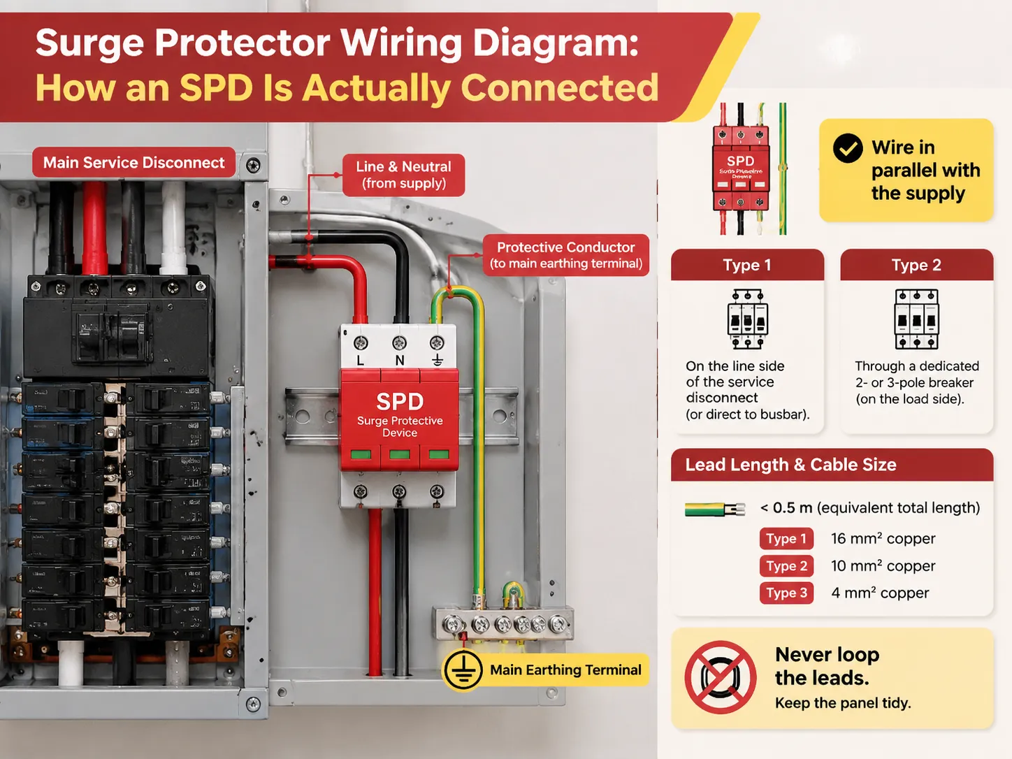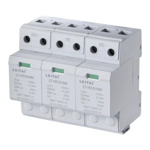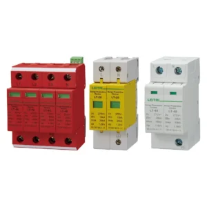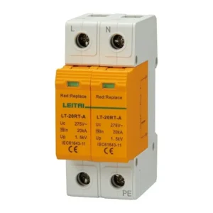

Type 1 surge protective devices (SPDs) and Type 2 devices are not essentially two strengths of the same product. The major difference between them is where each type can be connected with respect to the main overcurrent protective device, and depending on that position, the waveform to be survived. Type 1 is connected on the line side of the service disconnect and is tested for 10/350 µs partial lightning current. Type 2 is connected on the load side and is tested for 8/20 µs surges and transients.
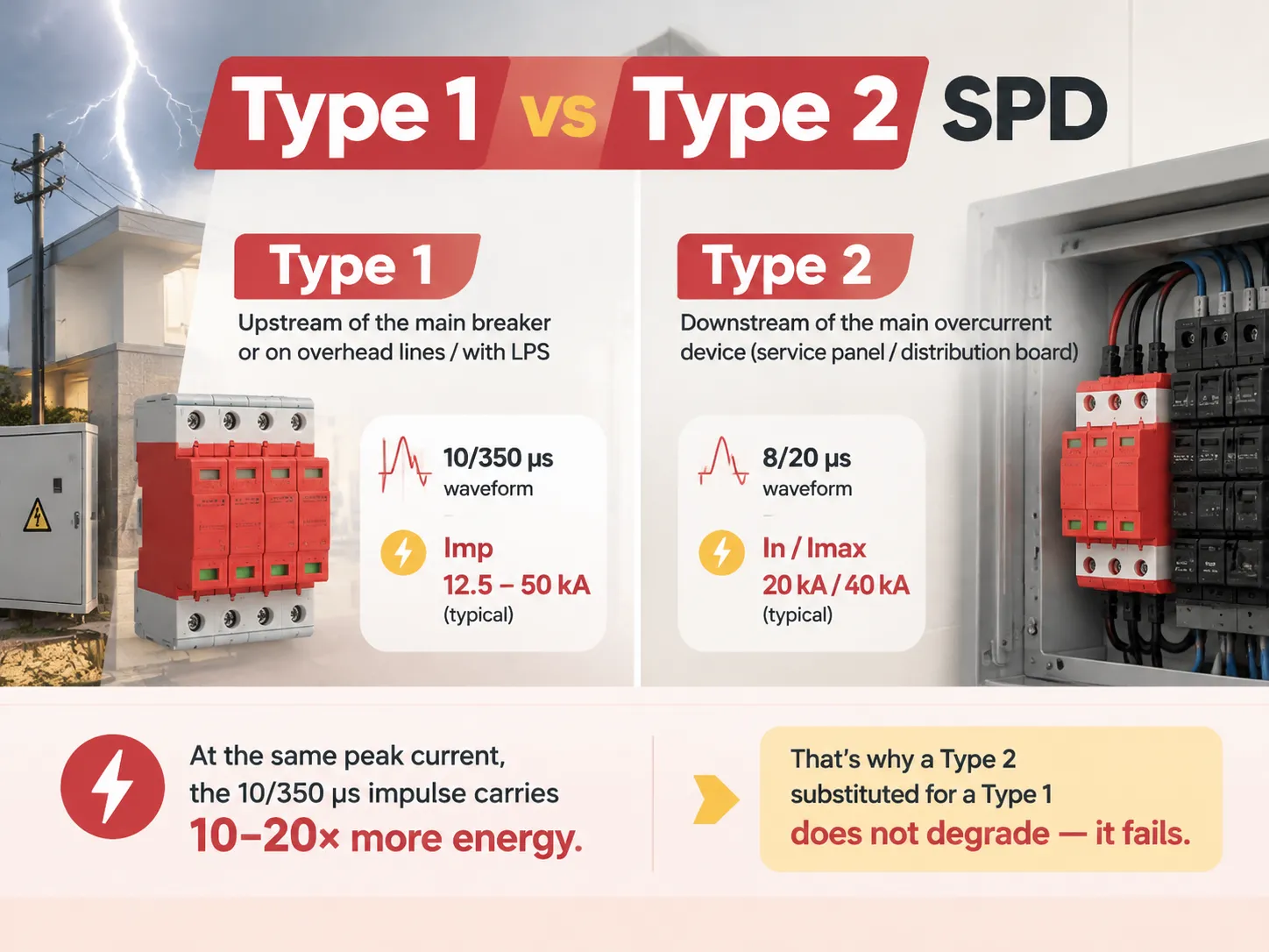
The most crucial part of selecting the type of SPD is the location of the SPD. If it is located upstream of the main breaker, or it connects into the service that is fed by overhead lines or a building that has lightning protection, you need Type 1 rated by Iimp according to the 10/350μs waveform, usually in the range of 12.5-50 kA. If it is located downstream of the main overcurrent device, then you need Type 2 rated by In and Imax according to the 8/20μs waveform, typically banks of 20 kA or 40 kA. The 10/350μs impulse will have ten to twenty times more energy at the same peak current. That is why it is not that Type 2 will not be damaged if used instead of Type 1, it will just fail.
Where Each One Connects
The classification is a rule of location with an effect in physics. Type 1 is categorized for the connection from the supply transformer secondary to the line side of the service disconnect overcurrent device and can also work on the load side. Type 2 refers to the load side of the first overcurrent device. According to the same brand policy, you can purchase two similar-looking devices that sit on the same DIN rail but are not interchangeable in the same location.
The reason why the hard device is put in front is the energy density. The peak of surge current is at the service entrance where the conductors carrying partial lightning current reach the interior of the building. In IEC 62305-4 terms this moment corresponds to LPZ 0→1 boundary where external lightning protection system of the building connects to electric installation. A spark gap or gas discharge tube deals successfully with this incident whereas a metal oxide varistor fails at such energy level.
The benchmark for a serious service-entrance device is not the kA figure printed largest on the box, it is whether the 10/350 µs test data exists. A Type 1 arrester rated Iimp 25 kA on the 10/350 µs waveform with a 1.4 kV L-N protection level is a real Type 1 device: the impulse current rating is quoted against the long-duration waveform, the housing is IP20 and UL94 V0, and the internal thermal disconnector carries a visible failure indicator. A supplier quoting only Imax on a device claimed to be Type 1 has not supplied a Type 1 device.
The Waveform Difference That Explains Everything
The typical current waveforms are represented by two shapes, which define the shape of the argument.
- The well-known 10/350 µs waveform rises quickly to its peak in approximately 10 microseconds and then takes 350 µs to decay. The significant factor in comparing this waveform with other ones is its tail, which allows it to imitate the current caused by a lightning strike.
- The second type of waveform commonly used has the shape of 8/20 µs: it rises in 8 microseconds and decays in 20 microseconds. This shape is mostly to be found in what is known as switching and induced currents that are present all around us.
At the same peak values, 10/350 µs currents can produce ten to twenty times more energy than 8/20 µs currents. This means that Imax values that we calculate do not allow any comparisons of different current types. For instance, the statement that “my Type 2 is 40 kA and your Type 1 is only 25 kA” is inadmissible as it leads to two types being used in multiple situations and thus rated incorrectly.
Designers often underestimate that the physical arrangements of the terminals of the installations matter. They must understand that the position from the busbar to the SPD and from the SPD to the earth must be as short and direct as it is possible.That is a routing decision made before a single terminal is tightened, and the step-by-step wiring layout for a surge protector matters more to the installed performance than the difference between two brands of equivalent rating.
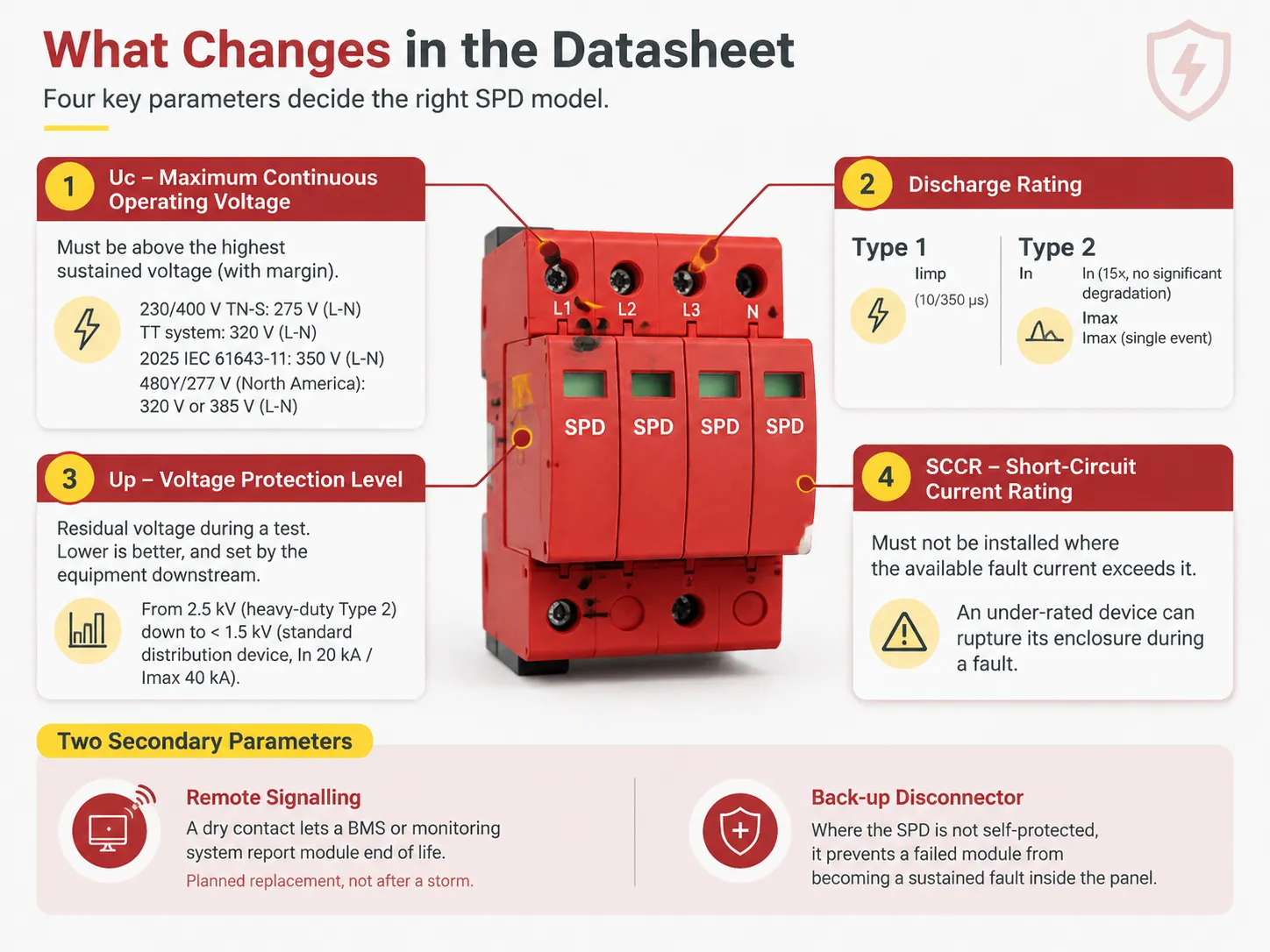
What Changes in the Datasheet
When you have determined the type of model required by the location, four parameters will define your model.
- Uc, the maximum continuous operating voltage, must be higher than the highest continuous voltage that the model will encounter, with some safety margin included. In a TN-S system operating at voltage levels of 230/400 V, the typical low voltage to neutral level is 275 V; while TT systems, as well as the 2025 revision of IEC 61643-11, define levels of 320 V and 350 V, respectively. At the other end, the common voltage levels to be expected in a North American 480Y/277 V system are either 320 V or 385 V.
- The discharge rating is defined. For type 1, the rating Iimp applies for time intervals of 10/350 µs; whereas for type 2 the rating In has to be determined since it defines the current that the SPD can withstand through repeated tests; Imax is also important for large single events.
- The voltage protection level must also be indicated. This is the voltage that remains at the SPD output during tests and is always lower than the voltage determined by the impulse strength of the SPD between its input and output. Therefore there may be significant differences in device types regarding their voltage levels: it may vary from 2.5 kV for heavy-duty type 2 devices and much less than 1.5 kV for a regular distribution device, which reaches In of 20 kA and Imax of 40 kA.
- The SCCR has to be provided as well; the SPD must not be installed in a place where the available short-circuit current is higher than the SCCR value.
There are two secondary metrics to monitor, as they are inexpensive to implement and costly to redo. The first of these is remote signalling through a dry contact that enables the BMS or the monitoring system to report the module’s end of its life. Planned replacement is very different from finding out that the module has failed only after a storm occurs. The second is a dedicated backup disconnector that prevents a defective module from being a permanent defect in the panel if the SPD does not have its own protection.
Type 1+2: When One Device Does Both
Together systems can be regarded as independent single units certified with both approaches because of two practical issues: the need for space and the need for separation.
Separated cascaded devices cannot be positioned closer than 10 m in conductor, or separated with decoupling reactor of 10 uH as well as the top device must polarize the signals effectively before the bottom device senses the information. In a limited space access, however, achieving this distance is impossible. A combined Type 1 and Type 2 device that satisfies both certification requirements offers no separation distance to obey since only one device has to be installed.
The parameters differ from a pure Type 1 in a way worth reading carefully. A Type 1+2 combined unit tested at Iimp 25 kA on 10/350 µs and simultaneously at In 25 kA / Imax 50 kA on 8/20 µs gives a rated 1.2 kV protection level at 275 V Uc, with variants for 350 V and 440 V systems — useful where the same panel design has to serve several supply voltages. The drawback here is that using an integrated device means losing the opportunity to position a smaller and cheaper Type 2 closer to the load, where the last 30–40 percent of dissipated energy is truly lost.
How to Choose Without Overthinking It
First try answering the four questions in order and you will generally get the answer quickly, usually already at the first or second question.
- Does the building have a lightning protection system outside, or the electricity is supplied with the overhead transmission lines? If yes, Type 1 or Type 1 and 2 should be used as a minimum at the point of supply. That is not optional under IEC 60364-5-53 and IEC 62305-4 rules.
- Is the supply fully underground, and there is a lightning protection system missing? If so, Type 2 is the minimum for the main distribution board. Some objects even start from that level voluntarily. Nevertheless, valuable or critical loads should always be fitted with combined solution.
- What is going beyond the board? If there are sensitive electronics far from the supply point, long cable runs, motor drives with the controls, or other equipment that can suffer losses, there should be additional Type 2 followed by Type 3 installed besides the first one.
- What is the existing fault current at the installation site? This is the question which is very frequently responsible for having to change the scheme even from the electrical point of view as it determines the bottom line of the SCCR.
On a residential service the numbers stay modest, and the sizing logic is mostly about exposure and panel space rather than kA. The sizing approach for a 200 A service is a useful worked example of that, because it walks through why service amperage does not translate into a surge rating and what to look at instead.
Applications Where the Choice Is Decided for You
Certain systems by their nature remove much of the controversy. In such environments the place of operation determined by artifice or by simple rules of understanding well-defined object is the cause of all confusion.
- Industrial locations. In this environment the switching processes can be seen constantly present there. That is why the different types of systems work there but the main challenge is to distinguish the moment when the switching process stops being a regular affair. This environment is typical for industries with long production flows, PLC control and lots of VFD motors.
- Solar generation facilities. Long power circuits set on the ground are extremely risky in the terms of impact of surges and lightings. Because of that the dc side requires some specific solutions when the ac side performs quite naturally following the standard regulation.
- Transport systems. The work of the switching system of the power supply system in railways requires such kinds of devices that comply not only with the common requirements but with numerous EMC standards as well as with other restrictions that greatly limits the choice of the available vendors.
- Telecommunication and data. The operation principle of the devices used to supply power is similar to that of the systems above, however the signal side requires special measures to be implemented.
Industrial installations are where coordination actually gets specified as a package rather than as a single device purchase, and the reasoning is set out in this overview of what surge protection for industrial manufacturing has to cover across switchgear, control panels and production equipment.
Frequently Asked Questions
Do I need Type 1 or 2 SPD?
Determine depending on the place of installation. If the SPD is connected on the line side of the master service disconnect or if the building has a lightning protection system or an overhead electrical supply, Type 1 is the right choice. In case it is installed on the load side of the main overcurrent device, in a distribution board or in an electrical distribution board, Type 2 should be selected. In most ordinary buildings, Type 2 is required in the distribution board and Type 1 can only be used in areas exposed to direct lightning strikes.
Can a Type 1 SPD be used as a Type 2?
Usually, Type 1 devices are designated for the line side and they can be used on the load side, so the placement rule doesn’t prevent them from use in this capacity. The limitations are a matter of practical limitations, not electrical ones: in general, a Type 1 is much larger physically and its price is much higher than a similar Type 2. In addition, its protection level is much better (2.0-2.5 kV) than a relatively good Type 2 offers and using it in the downstream application is not reasonable since it does not provide better clamping but is more expensive. It’s necessary to read the manufacturer’s instruction before deciding whether this approach is suitable or not.
Which is better, Type 1 or Type 2 surge protector?
Neither device performs the same function. They offer protection at different points in the installation and cannot substitute for one another. The most common grave specification mistake in this field is the combination of a Type 2 alone with a Lightning Protection System (LPS) because the current reaches the Type 2 with a very high value, far above its rated capacity. For applications at a location exposed to lightning, a Type 1 at the service coupled with a Type 2 at the circuit board level and a Type 3 at the equipment is the correct selection.
What is Type 1, 2, and 3 SPD?
IEC 61643-11 describes three classes of protection devices. Class 1 protective devices are positioned at the service entrance and before the main disconnector (i.e. on the supply side) and are tested using a waveform of 10/350 microseconds and rated according to Iimp. Class 3 protective devices are installed on the load side of the main overcurrent device (fuse or circuit breaker) and are tested using a waveform of 8/20 microseconds and rated, according to In and Imax. Class 3 protective devices are installed as close to the electrical equipment as possible, and at least 10 meters away from the service and are tested using a more complex waveform (combination waveform). Final tested voltage is defined according to Uoc. Notice that a class 3 protective device cannot operate without an upstream class 2 protective device.
References
- International Electrotechnical Commission — IEC 61643-11, surge protective devices connected to low-voltage power systems
- UL Standards & Engagement — UL 1449, Surge Protective Devices, fourth edition
- NFPA 70, National Electrical Code — Article 242 and Section 230.67(C), Type 1 or Type 2 at services
- Legrand — surge protection device selection and installation guidance
- Siemens — surge protective device technical documentation and test data
Conclusion
The type label serves as the installation limit, while the waveform behind it serves as the cause of the limit’s existence. Look at where the device is connected and make sure that the data sheet has the correct waveform — Iimp for a type 1 is 10/350 µs, while In and Imax for a type 2 is 8/20 µs — before looking at any kA numbers. The next important things to think about are protection level, SCCR, and remote signaling, as this is what sets apart the two somewhat similar devices, with coordination with the downstream stages being the biggest factor determining how much of the surge actually reaches your equipment.